Device and method for dynamically testing excavation resistance of excavator
A technology for dynamic testing and excavators, which is applied in the directions of measuring devices, testing of machines/structural components, surveying and navigation, etc. It can solve problems such as complex model building, cumbersome calculations, and inability to fully reflect the digging status of excavators, and achieve Guaranteed measurement range, improved measurement accuracy, good measurement accuracy and effectiveness
- Summary
- Abstract
- Description
- Claims
- Application Information
AI Technical Summary
Problems solved by technology
Method used
Image
Examples
Embodiment 1
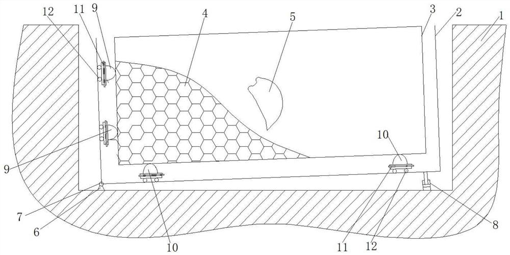
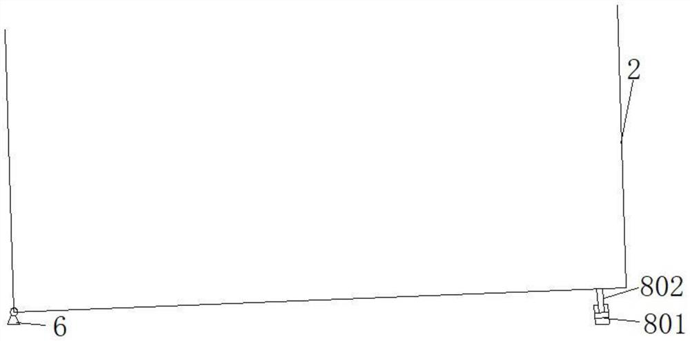
[0042] Such as figure 1 and figure 2 As shown, a dynamic test device for excavator excavation resistance includes a soil tank seat 2 arranged in the foundation pit 1, and the bottom side of the soil tank seat 2 is hinged with the bottom surface of the foundation pit 1 An angle sensor is also provided, and an inclination adjustment assembly 8 is arranged between the other side of the bottom and the bottom surface of the foundation pit 1. The soil tank seat 2 is provided with a soil tank 3, and the outer peripheral wall of the soil tank 3 A number of movable horizontal force sensors 9 are provided between the inner peripheral wall of the soil tank seat 2, and several horizontal force sensors 9 are arranged between the outer bottom wall of the soil tank 3 and the inner bottom wall of the soil tank seat 2. A movable vertical force sensor 10; the soil tank 3 is filled with a working medium 4 for the dynamic excavation resistance test, and the outer wall of the soil tank seat 2 an...
Embodiment 2
[0058] The difference between this embodiment and the first embodiment is that another bottom structure of the earth tank seat is provided.
[0059] The outer bottom wall of the soil tank seat 2 is provided with several guide shallow grooves, the guide shallow grooves are provided in one-to-one correspondence with the piston rod 802, and the guide shallow grooves are long strips arranged along the length direction. shallow groove; the end of the piston rod 802 is also provided with a rolling ball, and the rolling ball abuts in the shallow guide groove.
[0060] The setting of the guide shallow groove can play the role of guiding and limiting, and cooperate with the rolling ball to ensure that the soil tank seat 2 can be lifted or lowered smoothly without shaking.
Embodiment 3
[0062] Based on the excavator excavation resistance dynamic testing device described in Embodiment 1 and Embodiment 2, this embodiment provides a dynamic testing method for excavator excavation resistance, including the following steps:
[0063] (1) preparatory work, four vertical force sensors 10 are installed at the four corners of the bottom of the soil tank 3, and are used to measure the force in the vertical direction, and four horizontal force sensors are installed at the four corners of the side walls of the soil tank 3 9. It is used to measure the force in the horizontal direction, and then the working medium 4 is filled, and the filling height is not lower than the installation height of the uppermost horizontal force sensor 9; the sensor mounting seat and these force sensors are connected with the soil Slot 3 is relatively fixed;
[0064] (2) sensor calibration, after loading is completed, the four vertical force sensors 10 at the bottom of the soil tank 3 are initia...
PUM
 Abstract
Description
Claims
Application Information
 - R&D
- Intellectual Property
- Life Sciences
- Materials
- Tech Scout
- Unparalleled Data Quality
- Higher Quality Content
- 60% Fewer Hallucinations
Browse by: Latest US Patents, China's latest patents, Technical Efficacy Thesaurus, Application Domain, Technology Topic, Popular Technical Reports.
© 2025 PatSnap. All rights reserved.Legal|Privacy policy|Modern Slavery Act Transparency Statement|Sitemap|About US| Contact US: help@patsnap.com


