Multi-channel wave module and assembling method thereof

A multi-channel, wavelength division technology, applied in optical components, light guides, optics, etc., can solve problems such as damage, achieve simple coupling methods, improve product yield, and improve coupling efficiency

Inactive Publication Date: 2022-04-05
SUZHOU TFC OPTICAL COMM CO LTD
View PDF0 Cites 0 Cited by
  • Summary
  • Abstract
  • Description
  • Claims
  • Application Information

AI Technical Summary

Problems solved by technology

[0003] In the existing technology, manufacturers of transceiver components generally carry out coupling alignment and welding of multi-channel WDM components through active coupling, which requires high-precision coupling welding equipment, equipped with high-precision source meters and power meters, and requires There is a certain risk of damage if the bare chip is powered on multiple times

Method used


Image

  • Multi-channel wave module and assembling method thereof
  • Multi-channel wave module and assembling method thereof
  • Multi-channel wave module and assembling method thereof

Examples


Embodiment Construction

[0026] The specific embodiments of the present invention will be described in detail below in conjunction with the accompanying drawings, but it should be understood that the protection scope of the present invention is not limited by the specific embodiments.

[0027] Unless expressly stated otherwise, throughout the specification and claims, the term "comprise" or variations thereof such as "includes" or "includes" and the like will be understood to include the stated elements or constituents, and not Other elements or other components are not excluded.

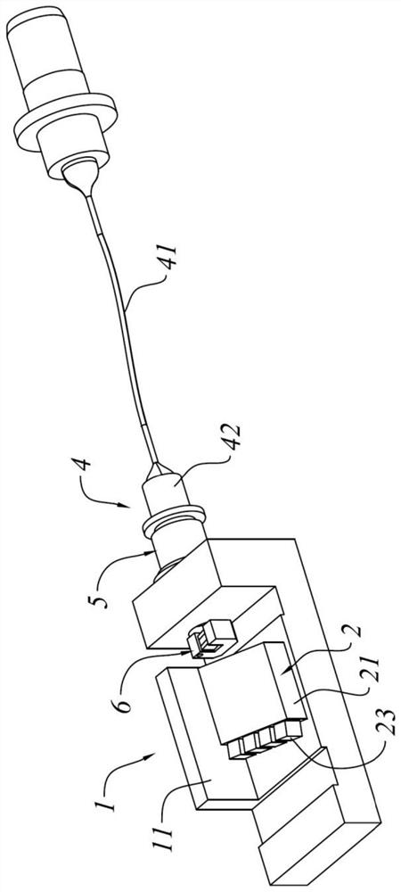
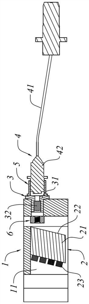
[0028] Please refer to figure 1 with figure 2 As shown, a multi-channel wavelength division component in an embodiment of the present invention includes: a base 1 , a wavelength division multiplexing element 2 , a lens element 3 and an optical fiber element 4 .

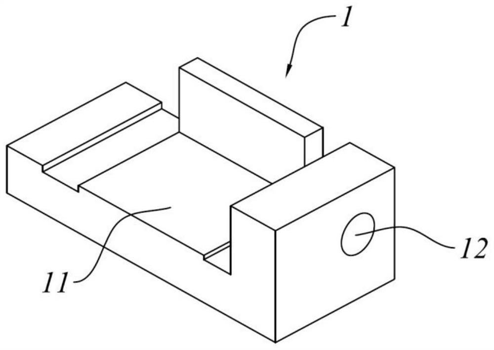
[0029] Wherein, the base 1 has a receiving groove 11 and an installation through hole 12 corresponding to the receiving groove 11 . The wavelength division mul...


PUM


Abstract

The invention discloses a multi-channel wavelength division subassembly, which comprises a base, a wavelength division multiplexing element, a lens element and an optical fiber element, the base is provided with an accommodating groove and a mounting through hole; the wavelength division multiplexing element is fixed in the accommodating groove, the wavelength division multiplexing element comprises an optical substrate, a reflector plate and a filter plate, and the reflector plate and the filter plate are respectively arranged on two opposite side surfaces of the optical substrate; the lens element comprises a lens branch pipe and a collimating lens mounted in the lens branch pipe, and the lens branch pipe is fixed in the mounting through hole; the optical fiber element comprises an optical fiber and an optical fiber connector connected with the optical fiber, the optical fiber connector is installed on the lens branch pipe through an adjusting ring, and the adjusting ring is used for limiting the relative position between the optical fiber connector and the collimating lens. According to the multichannel wavelength division component provided by the invention, a light spot coupling mode can be adopted to replace traditional active coupling, the position, angle and light spot size of emergent light can be adjusted through the adjusting ring, and the coupling efficiency of subsequent active coupling can be improved.

Description

technical field [0001] The invention relates to the field of optical communication equipment, in particular to a multi-channel wavelength division component and an assembly method thereof. Background technique [0002] With the development of optical fiber communication technology, the integrated manufacturing of optical devices has become the key to the progress of optical information technology. In high-speed optical communication products, multi-channel wavelength division components are very commonly used. They are usually packaged together with transceiver components to realize functions such as photoelectric conversion and wavelength division multiplexing. [0003] In the existing technology, manufacturers of transceiver components generally carry out coupling alignment and welding of multi-channel WDM components through active coupling, which requires high-precision coupling welding equipment, equipped with high-precision source meters and power meters, and requires ...

Claims


Application Information

Patent Timeline
Patent Type & Authority Applications(China)
IPC IPC(8): G02B6/293
Inventor 罗志国
Owner SUZHOU TFC OPTICAL COMM CO LTD
Why Eureka
Try Eureka