Cutter coating process and equipment

A tool and process technology, applied in the field of tool coating technology and equipment, can solve the problems of tool edge dulling, etc., to achieve the effect of ensuring sharpness, reducing thickness, and avoiding dullness

Pending Publication Date: 2022-04-08
SONGSHAN LAKE MATERIALS LAB
View PDF10 Cites 1 Cited by
  • Summary
  • Abstract
  • Description
  • Claims
  • Application Information

AI Technical Summary

Problems solved by technology

[0003] However, in order to ensure the bonding force between the carbon film layer and the tool substrate, it is necessary to set a metal carbide with sufficient thickness as a transition layer on the surface of the tool substrate, which will cause the cutting edge of the tool to become blunt, contrary to the original intention of coating the hard film layer

Method used


Image

  • Cutter coating process and equipment
  • Cutter coating process and equipment
  • Cutter coating process and equipment

Examples


Embodiment 1

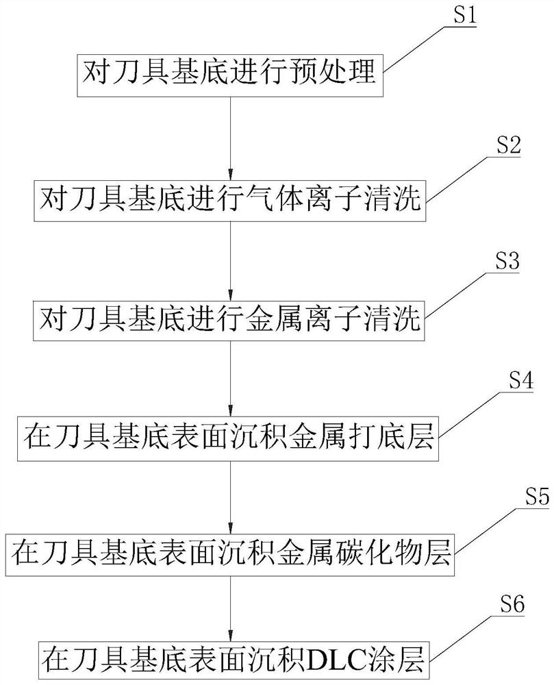
[0048] see figure 1 , the present embodiment provides a tool coating process for cutting tool base 500 (see Figure 5) to prepare a carbon film layer on the surface. In the present embodiment, the carbon film layer is a DLC (Diamond Like Carbon, diamond-like carbon) coating, and the tool coating process is a tool DLC coating coating process, comprising the following steps:

[0049] S1, perform pretreatment on the cutter base 500 .

[0050] Specifically, use the sharpened cutter as the cutter base 500, clean the cutter base 500 with alcohol and deionized water successively, then dry the cleaned cutter base 500 with a drying furnace, and place it in the drying furnace for use .

[0051] S2, cleaning the cutter base 500 with gas ions.

[0052] Specifically, the cutter base 500 is placed on the hanger in turn, and put into the turntable 100 in the DLC coating equipment with the hanger (see Figure 4 )superior. Evacuation of the DLC coating equipment and accompanying heating ...

Embodiment example

[0085] The specific implementation cases are compared as follows:

Embodiment

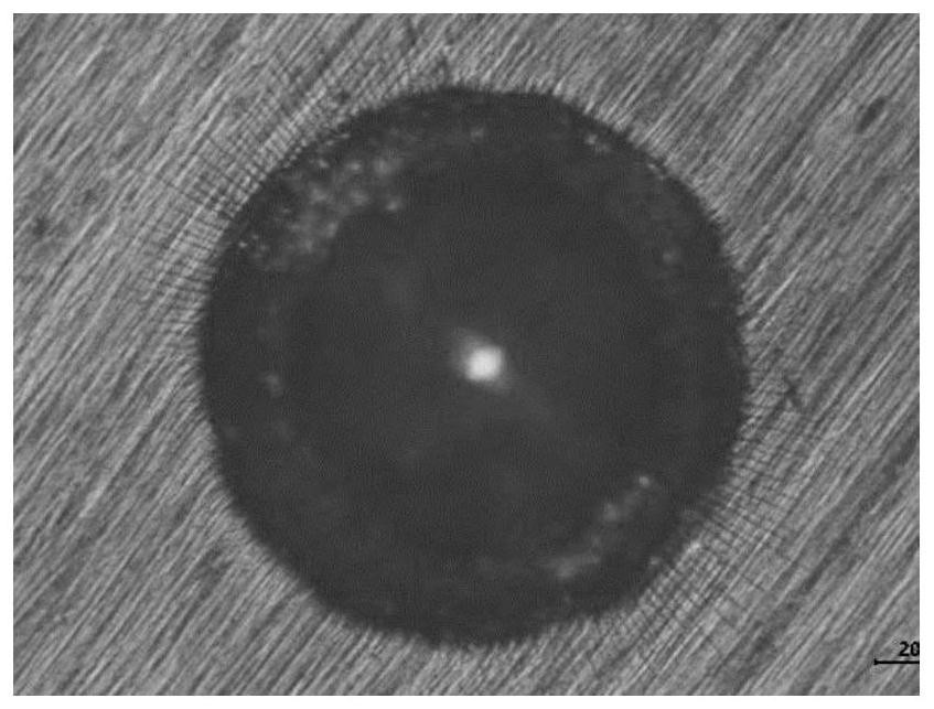
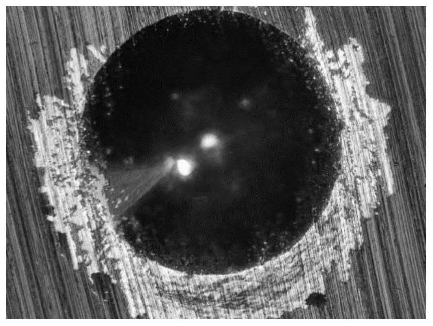
[0087] see figure 2, using the above tool DLC coating process to coat the DLC coating on the surface of the tool base 500, the hardness of the DLC coating was measured by a nanohardness tester to be 15Gpa, and the thickness of the DLC coating was measured by the ball pit method to be 0.6 μm. The adhesion of the DLC coating was measured by the indentation method. There were fine radial cracks around the indentation, but no coating peeling off, indicating that the DLC coating was well combined with the tool substrate 500, and the adhesion was H1.


PUM

PropertyMeasurementUnit
thicknessaaaaaaaaaa
thicknessaaaaaaaaaa
thicknessaaaaaaaaaa

Abstract

The invention provides a cutter coating process and equipment, and relates to the field of metal surface treatment. The cutter coating process comprises the following steps: pretreating a cutter substrate; performing gas ion cleaning on the tool substrate; carrying out magnetron sputtering on the metal target material by adopting a high-energy pulse magnetron sputtering technology to form metal ions, and carrying out etching cleaning on the tool substrate by matching with the pulse control metal ions of the pulse bias; and a metal carbide layer and a carbon film layer are sequentially deposited on the surface of the tool substrate, and the thickness of the metal carbide layer is not larger than 500 nm. After the tool substrate is subjected to gas ion cleaning, the tool substrate is subjected to metal ion etching cleaning, the binding force between the tool substrate and the carbon film layer can be effectively increased, and therefore the thickness of a metal carbide layer is reduced on the premise that it is guaranteed that the tool substrate and the carbon film layer are stably combined, the thickness of the metal carbide layer is not larger than 500 nm, and the tool substrate is not prone to being damaged. The cutting edge is prevented from being blunt due to over-thickness, and the sharpness of the cutting edge is ensured.

Description

technical field [0001] The invention relates to the field of metal surface treatment, in particular to a tool coating process and equipment. Background technique [0002] Kitchen knives are mainly used to cut meat, vegetables, and fruits. They are usually made of steel such as stainless steel. Because of their high friction coefficient, the cutting edge tends to become blunt during use and requires frequent regrinding. In order to solve this problem, the common practice is to use the tool as the base to coat the surface of the tool with a hard film (such as a carbon film) to improve the hardness of the tool surface, reduce the friction coefficient of the tool surface, and make the tool surface Smooth and has good abrasion resistance. [0003] However, in order to ensure the bonding force between the carbon film layer and the tool substrate, it is necessary to set a metal carbide with sufficient thickness as a transition layer on the surface of the tool substrate, which will...

Claims


Application Information

Patent Timeline
Patent Type & Authority Applications(China)
IPC IPC(8): C23C14/02C23C14/06C23C14/16C23C14/35
Inventor 田修波郑礼清宋光耀李建伟王进平
Owner SONGSHAN LAKE MATERIALS LAB
Why Eureka
Try Eureka