Energy efficiency optimization method, device and equipment based on adaptive particle swarm power distribution

An optimization method and self-adaptive technology, applied in power management, baseband system components, instruments, etc., to achieve the effect of improving energy efficiency

Pending Publication Date: 2022-04-08
CENT SOUTH UNIV
0 Cites 0 Cited by

AI-Extracted Technical Summary

Problems solved by technology

[0007] In view of various problems that are not fully considered in the existing power allocation scheme, the purpose of the present invention is to provide an energy efficiency optimization method, device and equipment based on adaptive particle swarm p...

Method used

Wherein, in step S54, after the speed of each particle and the position are updated, the particle swarm that is newly generated will be carried out the fitness value calculation, according to the comparison of the particle fitness value and the particle fitness value before this time, from there The optimal position of each particle itself is selected as the local optimum, and the optimal positi...

Abstract

The invention discloses an energy efficiency optimization method, device and equipment based on adaptive particle swarm power distribution. The method comprises the following steps: initializing the position of each base station and the position of each user in a cell; calculating a large-scale fading factor beta and a covariance matrix R of a channel according to the position of each base station and the position of each user; receiving an uplink pilot signal, and estimating a channel by adopting an MMSE (Minimum Mean Square Error) method in combination with a large-scale fading factor beta and a covariance matrix R of the channel; deriving a signal to interference plus noise ratio (SINR) expression of the system according to the estimated channel, calculating frequency efficiency according to the Shannon capacity theorem, and establishing an energy efficiency optimization model of the system in combination with a power consumption model of the system; and for the energy efficiency optimization model, according to the optimization objective function, carrying out data power distribution of users on the basis of fixed pilot frequency power by using an adaptive particle swarm optimization algorithm. The energy efficiency of the system can be effectively improved, and the requirement of green communication is met.

Application Domain

Power managementBaseband system details +1

Technology Topic

Self adaptiveParticle swarm optimization +8

Image

  • Energy efficiency optimization method, device and equipment based on adaptive particle swarm power distribution
  • Energy efficiency optimization method, device and equipment based on adaptive particle swarm power distribution
  • Energy efficiency optimization method, device and equipment based on adaptive particle swarm power distribution

Examples

  • Experimental program(1)

Example Embodiment

[0080] The solution of the present invention will be further elaborated below with reference to specific embodiments and accompanying drawings.
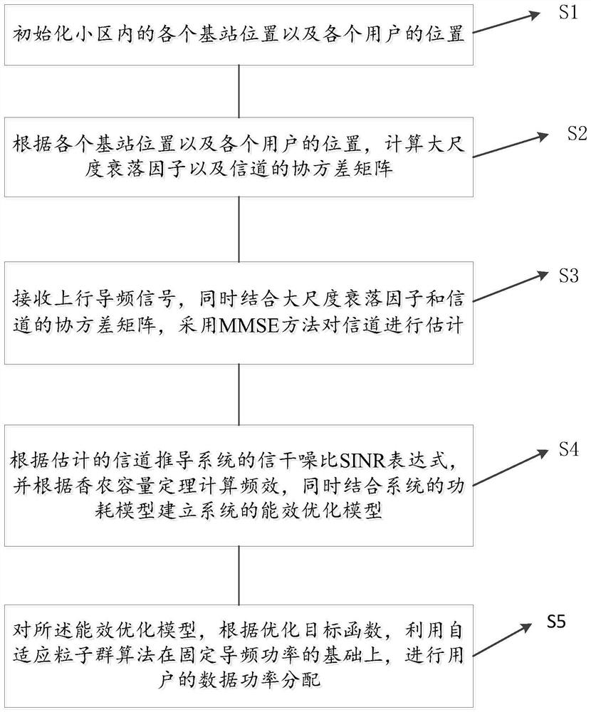
[0081] see figure 1 , the first embodiment of the present invention provides an energy efficiency optimization method based on adaptive particle swarm power distribution, which includes the following steps:
[0082] S1, initialize the location of each base station in the cell and the location of each user.
[0083] Among them, in an implementation manner, a total of 16 cells are set in this embodiment, and they are arranged according to 4*4. In order to overcome the interference between cells, the system adopts orthogonal pilots for users in the cells. Meanwhile, in order not to lose generality, the pilot frequency reuse factor of this system is set to f=4. Therefore, the pilot sequence used in this system can be expressed as In each cell, users are set by random distribution, while the minimum distance from the user to the base station is constrained, and the topological distance of the surrounding base stations is calculated for each user.
[0084] S2, calculate the large-scale fading factor β and the covariance matrix R of the channel according to the position of each base station and the position of each user.
[0085] In this example, consider a multi-cell multi-user massive MIMO system, which is composed of L square cells. In each cell, a base station equipped with M antennas is set up in the center of the cell, and serves K single-antenna users randomly distributed in the cell (where K<
[0086]
[0087] in, Represents small-scale fading and obeys a circularly symmetric complex Gaussian distribution, namely CN~(0,I M ).
[0088] in, is the large-scale fading factor, which is generally expressed as
[0089]
[0090] here represents shadow fading, its logarithm follow a Gaussian distribution in represents the distance from the ith user in cell l to the base station in the center of cell j, r0 represents the radius of the cell, and α represents the path loss coefficient during signal transmission; in particular, The change is slow and easy to track in the coherence time of several channels, so the coherence time of one coherence time is regarded as a constant.
[0091] In this embodiment, according to the set base station and user position, calculate the angle of arrival between the user and the base station, and obtain the covariance matrix R of the channel according to the approximate solution of the Gaussian local scattering model:
[0092]
[0093] where β is the large-scale fading factor, d H is the spatial distance of the antenna (generally set to half wavelength), M is the number of antennas configured by the base station, is the angle of arrival of the user.
[0094] S3: Receive the uplink pilot signal, and use the MMSE method to estimate the channel by combining the large-scale fading factor β and the covariance matrix R of the channel.
[0095] Among them, in the pilot transmission stage, the signal received by the base station in cell j It can be expressed as:
[0096]
[0097] here p jk represents the power of the kth user in cell j transmitting the pilot frequency, Pilot sequence transmitted for the kth user in cell j. It represents the additive white Gaussian noise at the receiving end of the base station, which obeys the independent and identical distribution CN (0~σ p ).
[0098] Multiply both sides of equation (4) by You can get:
[0099]
[0100] Due to the orthogonality of pilots, the value of the third term on the right side of the above equation (5) is 0, so the inter-cell interference can be removed, which is beneficial to channel estimation.
[0101] After the above operations, after the base station in the cell receives the pilot signal sent from the user, the base station can To perform channel estimation, this embodiment adopts the method of minimum mean square error (MMSE) estimation. Therefore, the channel estimation value between the kth user in cell l and base station j can be expressed as:
[0102]
[0103]
[0104]Therefore, in the uplink data transmission stage, the data received by base station j can be expressed as:
[0105]
[0106] In this embodiment, the received signal is received by using maximum ratio combining, that is, the received vector is:
[0107]
[0108] Therefore, the transmitted signal of user k in cell j can be expressed by the following formula:
[0109]
[0110] Among them, the first item is useful signal; the second item is intra-cell interference; the rest is inter-cell interference and other non-correlated noise.
[0111] S4, derive the SINR expression of the signal-to-interference-noise ratio of the system according to the estimated channel, calculate the frequency efficiency according to Shannon's capacity theorem, and establish an energy efficiency optimization model of the system in combination with the power consumption model of the system.
[0112] From the above-mentioned known process, the SINR, frequency efficiency SE, and energy efficiency EE expressions of the system are derived. in:
[0113]
[0114] Through Shannon's capacity theorem, it can be known that the lower bound of the frequency effect of the system can be expressed as:
[0115]
[0116] The purpose of this embodiment is to strive to improve the average energy efficiency in the system, once to achieve the development of green communication. So the optimization problem can be expressed as:
[0117]
[0118]
[0119]
[0120] in, Indicates the signal-to-interference-to-noise ratio of the kth user signal in cell j received by the base station in cell j, p li is the data power allocated to user i in cell j, V jk represents the received combined vector, represents the estimated value of the channel between the base station of cell j and the kth user in the cell, represents the estimated error matrix of the channel matrix, represents the noise power, for M j Unity matrix of order, EE UL Represents the system energy efficiency of the massive MIMO uplink transmission process, τ u Represents the length of the coherent block for transmitting uplink data, τ c represents the total length of the coherent block, M is the number of antennas equipped by the base station, p r is the power consumed by the RF link of the antenna during uplink data transmission, p s Static electrical power consumption during data transmission for massive MIMO systems, p max is the maximum electrical power of all users in each cell during uplink transmission. R min is the value set taking into account the minimum rate constraint.
[0121] S5 , for the energy efficiency optimization model, according to the optimization objective function, the adaptive particle swarm algorithm is used to allocate the data power of the user on the basis of the fixed pilot frequency.
[0122] Preferably, step S5 specifically includes:
[0123] S51, use the rand function and the upper and lower bounds of the set user data power to initialize the particles, of which in , the superscript is the number of iterations, and the subscript is the particle number; p 12 The subscript of the first number in the middle represents the cell number, and the subscript of the second number represents the user number in the cell.
[0124] S52, take the energy efficiency function EE as the fitness function, calculate the fitness of all the initialized particles, and initialize the local optimum and the global optimum
[0125] S53, update the speed and position of the particle and perform boundary processing:
[0126]
[0127]
[0128] Calculate the fitness value EE corresponding to the updated particle, and update the local optimal solution and the global optimal solution
[0129] S54, perform boundary condition processing. In the iterative process, the power constraint condition needs to be used as the boundary condition of the particle position, and the movement of the particle is bound within a certain range.
[0130] Among them, the update formula of particle velocity and position is:
[0131] V j (t+1)=V j (t)+c1*rand*(Gbest j -pop j (t))+c2*rand*(Zbest-pop j (t)) (15)
[0132]
[0133] In the formula, V j (t+1) represents the velocity value of the jth particle at the (t+1)th iteration, V j (t) represents the velocity value of the j-th particle at the t-th iteration, c1 is the individual learning factor, the iteration of the velocity is only related to the historical position of the particle itself, c2 is the social learning factor, and the iteration of the velocity is related to the entire particle swarm ω represents the weight factor. When ω is large, it is conducive to jumping out of the local minimum, which is convenient for global search, and when the inertia factor ω is small, it is conducive to accurate local search. Therefore, when the number of iterations is small, the value of ω is large, and when the number of iterations is large, the value of ω is small. Gbest j is the optimal position of the current position of the jth particle, Zbest is the optimal particle position of the entire particle swarm so far, pop j (t) represents the position parameter of the jth particle at the tth iteration.
[0134] The boundary processing methods for particle velocity and position are:
[0135]
[0136]
[0137] V(i,j) represents the velocity of the i-th particle in the j-th dimension. The boundary processing of the particle velocity can limit the particle's search speed in the solution space and fully search the solution space. pop(i,j) represents the displacement of the i-th particle in the j-th dimension, and the boundary processing of the position can strictly limit the particle motion in the solution space.
[0138] Among them, in step S54, after each particle velocity and position are updated, the fitness value of the newly generated particle swarm will be calculated. The optimal position of each particle itself is regarded as the local optimum, and the optimum position of the entire particle swarm is regarded as the global optimum. Since each iteration selects the individual optimum and the optimum value of the population, each iteration process only needs to store two A location parameter, which greatly reduces the requirements for storage space. At the same time, the boundary processing of particle velocity and position can make the search more effective and reliable.
[0139] S55, in order to prevent the particle swarm algorithm from being trapped in the local extreme value, the present embodiment combines the mutation operation of the genetic genetic algorithm, and adopts a 20% mutation probability to process the position of the particle:
[0140] k=ceil(LK*rand) (19)
[0141] pop(i,k)=rand*(pop max -pop min )+pop min (20)
[0142] S56, when the iteration termination condition is reached, the global optimal value is the optimal user data power allocation vector to be selected.
[0143] image 3 and Figure 4 It is the performance simulation result diagram of the embodiment of the present invention. As can be seen from the figure, under the same conditions, compared with the traditional power distribution algorithm, the present invention has a certain improvement in frequency efficiency, and also has a great improvement in energy efficiency. The performance of this method eventually shrinks gradually. Therefore, compared with the traditional allocation algorithm, the present invention has obvious performance improvement.
[0144] see Figure 5 , the second embodiment of the present invention also provides an energy efficiency optimization device based on adaptive particle swarm power distribution, which includes:
[0145] an initialization unit 210, configured to initialize the location of each base station and the location of each user in the cell;
[0146] a calculation unit 220, configured to calculate the large-scale fading factor β and the covariance matrix R of the channel according to the position of each base station and the position of each user;
[0147] The channel estimation unit 230 is configured to receive the uplink pilot signal, and at the same time, combine the large-scale fading factor β and the covariance matrix R of the channel, and use the MMSE method to estimate the channel;
[0148] The model establishment unit 240 is used for deriving the SINR expression of the signal-to-interference-noise ratio of the system according to the estimated channel, and calculating the frequency efficiency according to Shannon's capacity theorem, and establishing an energy efficiency optimization model of the system in combination with the power consumption model of the system;
[0149] The power allocation unit 250 is configured to use the adaptive particle swarm algorithm based on the fixed pilot power to allocate the data power of the user according to the optimization objective function for the energy efficiency optimization model.
[0150] The third embodiment of the present invention also provides an energy efficiency optimization device based on adaptive particle swarm power distribution, which includes a memory and a processor, where a computer program is stored in the memory, and the computer program can be executed by the processor , in order to realize the energy efficiency optimization method based on adaptive particle swarm power allocation as described above.
[0151] The specific embodiments described herein are merely illustrative of the spirit of the invention. Those skilled in the technical field of the present invention can make various modifications or supplements to the described specific embodiments or use similar methods to replace, but will not deviate from the spirit of the present invention or exceed the scope of the appended claims. defined range.

PUM

no PUM

Description & Claims & Application Information

We can also present the details of the Description, Claims and Application information to help users get a comprehensive understanding of the technical details of the patent, such as background art, summary of invention, brief description of drawings, description of embodiments, and other original content. On the other hand, users can also determine the specific scope of protection of the technology through the list of claims; as well as understand the changes in the life cycle of the technology with the presentation of the patent timeline. Login to view more.

Similar technology patents

Regenerative evaporative cooling air conditioner

Owner:SHANGHAI COTES AIR TREATMENT EQUIP CO LTD

Method and device for removing harmful gas through discharging plasmas

InactiveCN105944524AFacilitate degradation and absorptionImprove energy efficiency
Owner:黄华丽

Horizontal tuning frame type eddy current damper

ActiveCN112144689AImprove energy efficiencyImprove the problem of irregular deformation
Owner:湖南省潇振工程科技有限公司

Reduction-fusion iron manufacturing process for coal-bearing pellets

InactiveCN101492752AReduce the burden of steelmakingImprove energy efficiency
Owner:姚永林

Classification and recommendation of technical efficacy words

  • improve energy efficiency

Heat Transfer compositions

InactiveUS20090158771A1contribution be reduceimprove energy efficiency
Owner:INEOS FLUOR HLDG

Vehicle control apparatus

InactiveUS6930405B2improve energy efficiencyrecover kinetic energy
Owner:NISSAN MOTOR CO LTD

Safe power utilization management system and method based on edge calculation and big data analysis

InactiveCN111062651AReduce electrical safety risksImprove energy efficiency
Owner:南京中电科能技术有限公司

Data center energy saving system and method based on virtual IT resource distribution technology

ActiveCN103345298AImprove stability and longevityImprove energy efficiency
Owner:SHANDONG COMP SCI CENTNAT SUPERCOMP CENT IN JINAN
Why Eureka
Try Eureka