High-efficiency low-pollution plasma source

A plasma source, low-pollution technology, applied in the direction of plasma, electrical components, etc., can solve the problems of increasing the structure complexity and control difficulty of the Hall ion source, affecting the application range of the Hall ion source, and the small working discharge voltage range , to achieve the effects of improving the beam extraction efficiency and the ion energy in the beam, high beam extraction efficiency, and improving the utilization rate of the discharge current

Pending Publication Date: 2022-04-08
SOUTHWESTERN INST OF PHYSICS
View PDF10 Cites 2 Cited by
  • Summary
  • Abstract
  • Description
  • Claims
  • Application Information

AI Technical Summary

Problems solved by technology

[0005] In order to reduce the sputtering etching of the discharge ions on the magnetic poles, an additional magnetic field coil is often used at present to control the ion beam current characteristics in the channel by optimizing the magnetic field position, so as to achieve the purpose of reducing the ion flux bombarded to the wall. This method increases The structure complexity and control difficulty of the Hall ion source
The other is to extend the anode structure and extend the anode to the outside of the magnetic pole structure to reduce the bombardment of ions on the magnetic pole or side wall. Although the ion source of the anode layer can greatly reduce the etching of the magnetic pole, its working discharge voltage range is very small (300- 600V), affecting the application range of the Hall ion source

Method used


Image

  • High-efficiency low-pollution plasma source
  • High-efficiency low-pollution plasma source
  • High-efficiency low-pollution plasma source

Examples


Embodiment Construction

[0031] The present invention will be further described below by means of the accompanying drawings and specific embodiments. The accompanying drawings and descriptions are to be regarded as illustrative rather than restrictive, and the present invention is not limited to the disclosed specific embodiments, and various improvements made according to the spirit of the present invention are included in the scope of protection required by the claims of the present invention Inside.

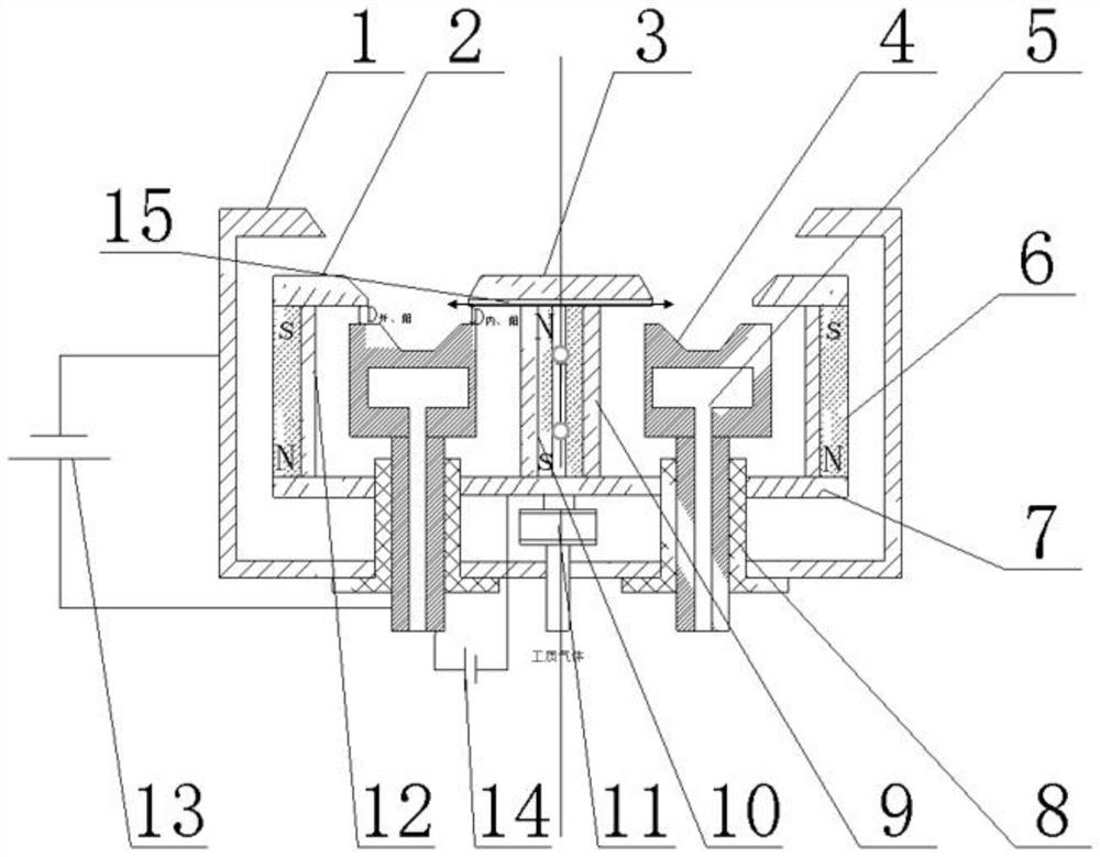
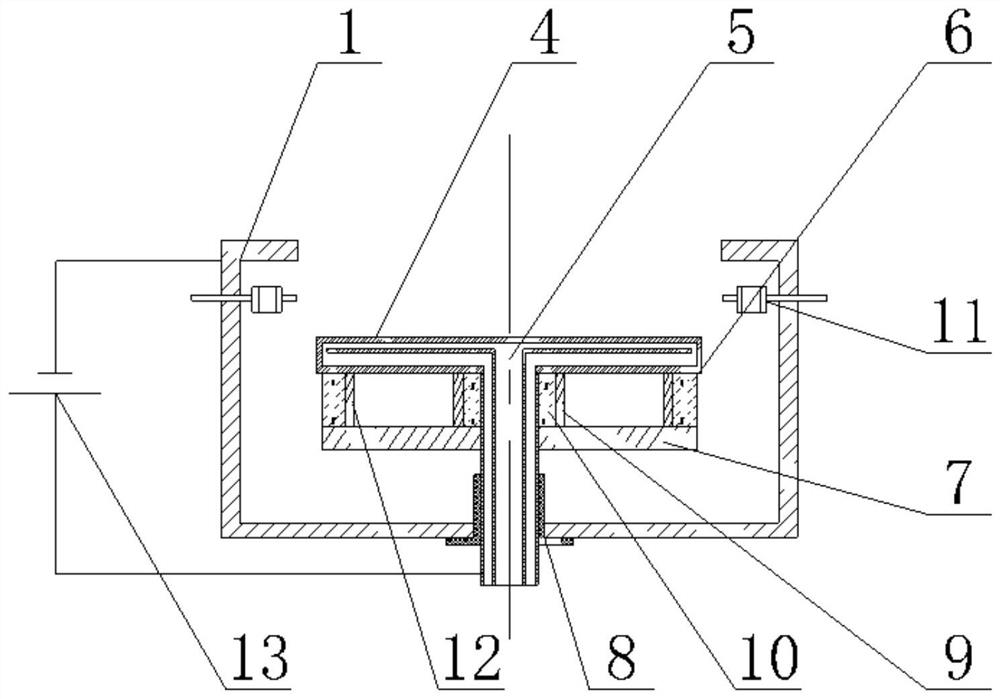
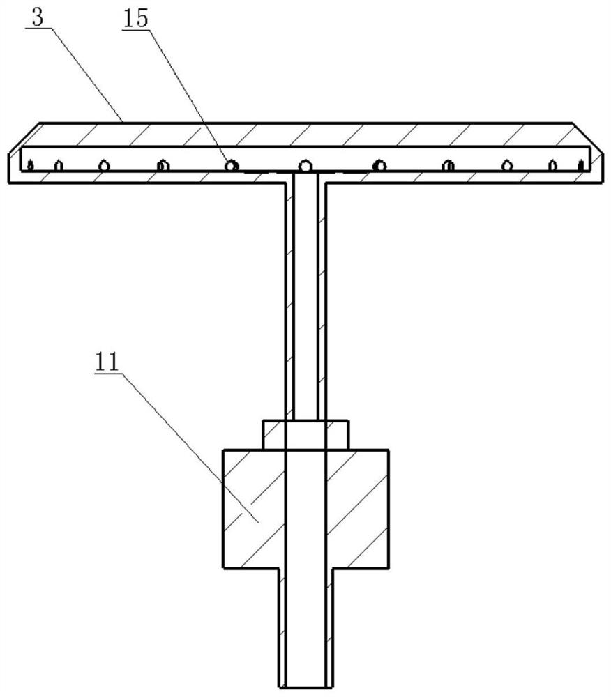
[0032] Such as figure 1 As shown, it includes a coaxially placed cathode 1 and a yoke base 7, an inner magnetic pole 3, an inner shield 9, an inner magnetic steel 10, an outer magnetic steel 6, an outer shield 12, and an insulating connection between the cathode 1 and the yoke base 7 Water-cooled anode 4;

[0033] Wherein, the bottom of the cathode 1 is processed with an installation groove for installing the insulator 8 and the water-cooled anode 4;

[0034] The yoke base 7 is located in the catho...


PUM


Abstract

The invention belongs to the technical field of plasma sources, and particularly relates to a high-efficiency low-pollution plasma source which comprises a cathode, a water-cooled anode and a magnet yoke base which are coaxially arranged, inner magnetic steel arranged at the center of the magnet yoke base, an inner shield which sleeves the inner magnetic steel, and outer magnetic steel and an outer shield which are fixedly mounted above the outer edge of the magnet yoke base, the magnet yoke base is positioned in the cathode; the water-cooled anode is connected with the cathode in an insulating manner; the magnetic force directions of the inner magnetic steel and the outer magnetic steel are opposite; and a discharge power supply A is connected between the cathode and the water-cooling anode. The inner magnetic pole and the outer magnetic pole of the plasma source are located at the suspension potential or different bias voltages are applied to a workpiece or a vacuum chamber respectively, and the potential is distributed by designing a discharge channel, so that self-sputtering of discharge plasma to the wall can be reduced and controlled, and the purposes of improving the utilization rate of discharge current and leading out ion energy are achieved.

Description

technical field [0001] The invention belongs to the technical field of plasma sources, and in particular relates to a plasma source with high efficiency and low pollution. Background technique [0002] Closed drift ion source is a low energy and large beam current (voltage 0-1000eV) ion source with high beam current density (≥2mA / mm 2 )), wide ion energy range (discharge voltage 30%-100%), simple structure, low maintenance cost, and suitable for oxygen, nitrogen, acetylene and corrosive gases, etc., widely used in ion beam etching, cleaning, activation and Auxiliary coating and other processes. [0003] The ion source is mainly composed of anode, cathode, and magnetic steel. Under the action of cathode and anode voltage, electrons move along the magnetic force line to the anode. Since there are almost orthogonal magnetic force lines and electric force lines in the area near the anode surface, in this intersection Under the action of the electromagnetic field, the electrons...

Claims


Application Information

Patent Timeline
Patent Type & Authority Applications(China)
IPC IPC(8): H05H1/24
Inventor 聂军伟陈庆川杨发展黄琪金凡亚但敏
Owner SOUTHWESTERN INST OF PHYSICS
Why Eureka
Try Eureka