
Ladle flow control device for preventing molten steel from being solidified

A ladle and molten steel technology, applied in the direction of casting melt containers, metal processing equipment, casting equipment, etc., can solve the problems of difficult control, molten steel pollution, and difficult judgment, and achieve the effect of avoiding secondary pollution

Pending Publication Date: 2022-04-12
HEBEI COLLEGE OF IND & TECH
View PDF0 Cites 0 Cited by
  • Summary
  • Abstract
  • Description
  • Claims
  • Application Information

AI Technical Summary

Problems solved by technology

However, in the published literature, the research focus of domestic and foreign scholars is still based on the automatic pouring process of drainage sand, and seldom carry out related research work without drainage sand.
However, refractory drainage sand is a foreign inclusion compared to molten steel. Once it enters molten steel, it will pollute molten steel and become the main source of impurities in continuous casting slabs, which will eventually affect the quality of steel products.
[0004] After the drainage sand is drained, how to prevent it from entering the molten steel and preventing it from contaminating the molten steel, there is currently no better solution other than using a manual sand tray to trap the drainage sand
Although this method can prevent the drainage sand from entering the tundish and contaminating the molten steel, it is difficult to judge and control when the drainage sand is finished and whether the molten steel flows into the long nozzle.

Method used


Image

  • Ladle flow control device for preventing molten steel from being solidified
  • Ladle flow control device for preventing molten steel from being solidified
  • Ladle flow control device for preventing molten steel from being solidified

Examples


Embodiment 1

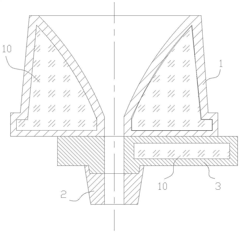
[0034] Such as figure 1 As shown, the heat insulation cavity 10 is filled with thermal insulation filler, the thermal insulation filler fills the thermal insulation cavity 10, and the thermal insulation filler is asbestos fiber. This embodiment can be used under the process condition that the residence time of molten steel in the ladle is less than or equal to 2h.

Embodiment 2

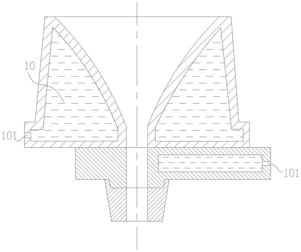
[0036] Such as figure 2 As shown, an air vent 101 is provided on the heat insulation cavity 10, and air is filled in the heat insulation cavity. The sides of the lower plate 3 are respectively provided with exhaust holes 101. When molten steel is loaded into the upper nozzle 1, the air can be discharged from the exhaust holes 101 after being heated and expanded to ensure that the pressure in the heat insulation chamber 10 is normal pressure. This embodiment can be used under the process condition that the residence time of molten steel in the ladle is 2-4h.

Embodiment 3

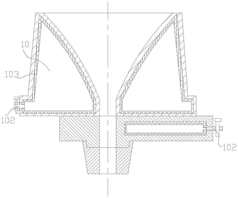
[0038] Such as image 3 As shown, the inside of the heat insulation chamber 10 is a vacuum, and an air nozzle 102 with a control valve is provided on the heat insulation chamber 10, and an air-proof layer 103 is fixed on the inner wall of the heat-insulation chamber 10, and the thickness of the air-proof layer 103 is 2-5mm. The materials include but are not limited to stainless steel, high-temperature refractory paint, etc. The purpose is to prevent external air from penetrating into the vacuum chamber through the upper nozzle 1 or the surface of the lower plate 3 after vacuuming, which will affect the vacuum degree. This embodiment can be used under the process condition that the residence time of molten steel in the ladle is 4-10h.

[0039] use as Figure 7For the corundum crucible of the size shown (its material meets the above requirements), the interlayer of the corundum crucible is filled with asbestos fibers, air and vacuumized respectively, and three kinds of heat pre...


PUM

PropertyMeasurementUnit
Angleaaaaaaaaaa
Refractorinessaaaaaaaaaa
Compressive strengthaaaaaaaaaa

Abstract

The invention discloses a steel ladle flow control device for preventing molten steel from solidifying, which comprises an upper nozzle fixed at the bottom of a steel ladle and a lower nozzle fixed on a lower sliding plate, and the upper surface of the lower sliding plate is connected to the bottom surface of the upper nozzle in a sliding manner, so that the lower nozzle can transversely move to be butted and communicated with the upper nozzle or be closed in a staggered manner with the upper nozzle. A pouring hole of the upper nozzle is in a horn shape with a large upper opening and a small lower opening, and the slope angle of the pouring hole is 50-80 degrees; the upper nozzle and the lower sliding plate are of hollow structures, heat insulation cavities are formed in the upper nozzle and the lower sliding plate, and the minimum thickness of the heat insulation cavities is not smaller than 20 mm. Molten steel enters the horn-opening-shaped steel ladle upper nozzle, the molten steel in the nozzle can be kept in a liquid state under the heat preservation effect of the upper nozzle and a heat insulation layer of the lower sliding plate and the supplement effect of heat of the high-temperature molten steel on the upper portion of the upper nozzle, and the problem that the molten steel is solidified to block the steel ladle nozzle, and finally the molten steel cannot be automatically cast is solved. And the problems of secondary pollution and the like caused by the use of the fire-resistant stuffing sand are avoided.

Description

technical field [0001] The invention relates to the field of steelmaking equipment, in particular to a ladle flow control device for preventing molten steel from solidifying. Background technique [0002] At present, in the metallurgical industry, sliding mechanisms are generally used to control the flow rate and switch of molten steel from ladle to tundish. The sliding mechanism changes the relative position of the upper and lower pouring holes through the sliding of the lower plate to realize the adjustment of the molten steel flow rate and switch. In order to improve the automatic casting rate of the continuous casting ladle (referred to as the self-opening rate), the ladle needs to be filled with refractory refractory drainage sand into the ladle upper nozzle before filling the molten steel. The drainage sand is located in the upper nozzle of the ladle between the lower plate of the ladle and the molten steel. After filling the molten steel into the ladle, when the drai...

Claims


Application Information

Patent Timeline
IPC IPC(8): B22D41/50B22D41/24
CPCB22D41/24B22D41/22B22D41/28B22D41/50
Inventor 曹磊陈敏韩提文孟延军曹珍杨彬张珊珊王朋
Owner HEBEI COLLEGE OF IND & TECH
Learn More