Control method for controlling deformation of 3D printing thin and high part

A technology of 3D printing and control method, applied in the direction of additive manufacturing, additive processing, etc., can solve the problems of easy deformation of 3D printing thin and high parts, and achieve the effect of reducing the risk of waterway wall breaking, small deformation, and reducing the degree of deformation

Pending Publication Date: 2022-04-12
上海镭镆科技有限公司
View PDF1 Cites 0 Cited by
  • Summary
  • Abstract
  • Description
  • Claims
  • Application Information

AI Technical Summary

Problems solved by technology

[0003] The purpose of the present invention is to solve the technical problem that 3D printing thin and tall parts are easily deformed in the prior art

Method used


Image

  • Control method for controlling deformation of 3D printing thin and high part
  • Control method for controlling deformation of 3D printing thin and high part
  • Control method for controlling deformation of 3D printing thin and high part

Examples


Embodiment 1

[0037] Taking an automobile connector core mold as an example, the workpiece is characterized by a total height H=280mm, a bow-shaped cross section, a string=50mm, and a bow height=18mm, and it is formed by printing with Corrax powder.

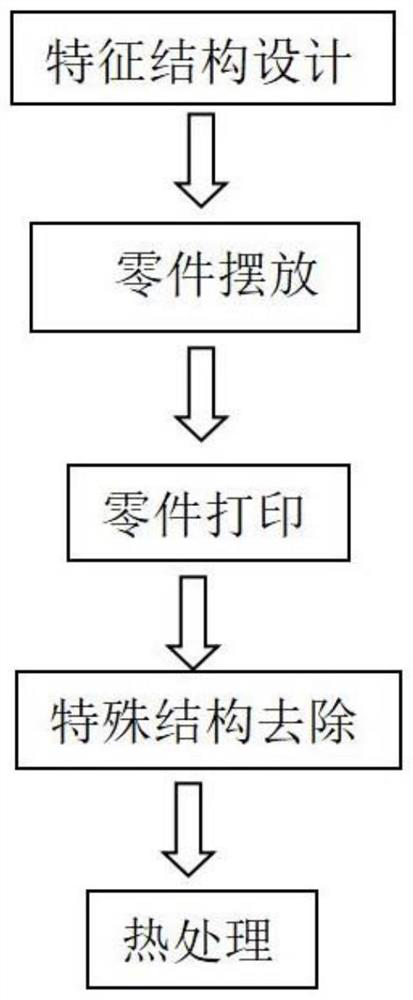
[0038] Step 1: Feature structure design;

[0039] The cross-section of the characteristic structure is still bow-shaped, the total height H=70mm, the bottom chord=46mm, the bottom bow height=17mm, the top chord=25mm, and the top bow height=8mm.

[0040] Step 2: Place the parts;

[0041] Place the string of the workpiece parallel to the blowing direction.

[0042] Step 3: Part printing;

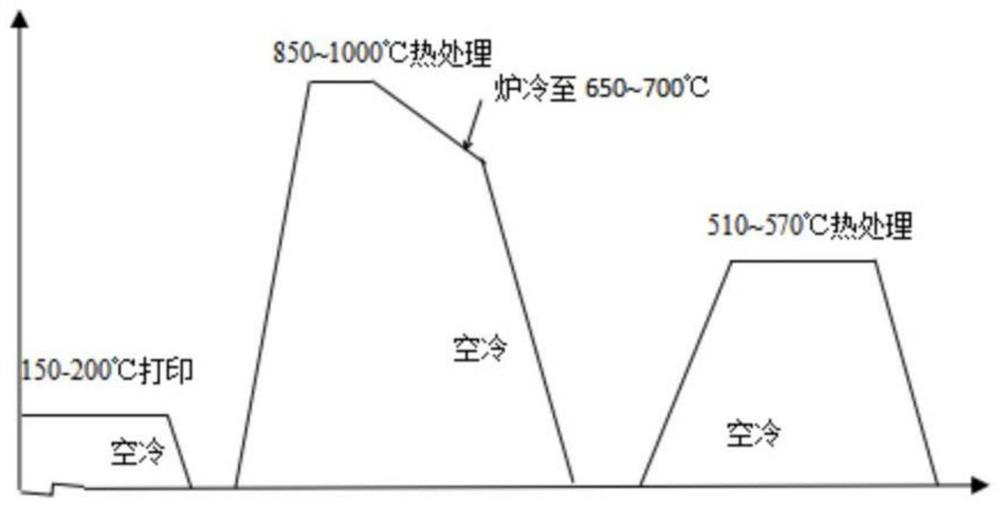
[0043] The substrate is heated to 150°C, and a checkerboard printing method is adopted, where the width of the checkerboard is 6mm, the printing power is 230W, and the speed is 780mm / s.

[0044] Step 4: feature structure cut;

[0045] After the forming is completed, the feature structure is removed by wire cutting

[0046] Step 5: heat treatment;

[0047...

Embodiment 2

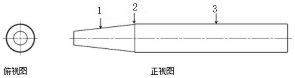
[0053] Taking a cosmetic eyebrow pencil packaged core mold as an example, the workpiece is characterized by a total height of H = 220mm, a circular cross section, and a diameter of 12mm, which is formed by printing with Corrax powder.

[0054] Step 1: Feature structure design;

[0055] The cross section of the characteristic structure is still circular, the total height H=60mm, the diameter of the bottom surface=11mm, the diameter of the top surface=8mm,

[0056] Step 2: Place the parts;

[0057] The cross-section of the workpiece is circular and placed normally

[0058] Step 3: Part printing;

[0059] The substrate is heated to 180°C, and a checkerboard printing method is adopted, where the width of the checkerboard is 6mm, the printing power is 280W, and the speed is 850mm / s.

[0060] Step 4: feature structure cut;

[0061] After the forming is completed, the feature structure is removed by wire cutting

[0062] Step 5: heat treatment;

[0063] The workpiece is subject...


PUM

PropertyMeasurementUnit
heightaaaaaaaaaa
heightaaaaaaaaaa
widthaaaaaaaaaa

Abstract

The invention relates to a control method for controlling deformation of a 3D printing thin and high part, and belongs to the technical field of 3D printing. According to the control method, through design of a feature structure, a conical feature structure is designed at the top of a thin and high part; the long axis direction of the workpiece is parallel to the air blowing direction or an included angle smaller than 45 degrees is formed between the long axis direction and the air blowing direction; when the part is printed and formed, the base plate is heated to 150-200 DEG C, and printing is conducted in a checkerboard mode; after forming is finished, the feature structure is removed; and in the heat treatment process, the workpiece is vertically placed, and two-step heat treatment is adopted. According to the 3D printing thin and high part machining method, the deformation degree of the thin and high part can be obviously reduced, the machining allowance of the thin and high part is reduced, and the risk of wall breaking of the water paths in the machining process of the thin and high part workpiece is reduced. And the extremely small deformation can ensure that the wall thickness of the waterway in the thin and high part is uniform, and guarantee is provided for the finished product quality of injection molding parts.

Description

technical field [0001] The invention relates to a control method for controlling the deformation of 3D printed thin and tall parts, belonging to the technical field of 3D printing. Background technique [0002] As an advanced industrial manufacturing technology, 3D printing technology integrates the advanced technologies of computer three-dimensional aided design, numerical control technology, laser processing, material science and other disciplines. Compared with the traditional mold manufacturing technology, this technology is constantly infiltrating, optimizing the production relationship of mold manufacturing, and greatly promoting the flexibility, high efficiency, low-carbon and environmental protection of mold technology. The net shape feature of 3D printing technology greatly shortens the production and processing cycle of molds. At the same time, the conformal waterway design of 3D printing technology has greatly improved the efficiency and quality of mold productio...

Claims


Application Information

Patent Timeline
Patent Type & Authority Applications(China)
IPC IPC(8): B22F10/28B22F10/38B22F10/66B22F10/64B33Y10/00B33Y40/20
Inventor 吴巧巧于鹏超邹阳张国良
Owner 上海镭镆科技有限公司
Why Eureka
Try Eureka