Joint driving device of wheel-legged robot, control method and wheel-legged robot

A wheel-legged robot and driving device technology, applied in the field of robots, can solve the problems of low transmission efficiency of hydraulic system, large energy consumption, large throttling power loss, etc., and achieve the reduction of the number of joint actuators, good impact resistance, and structural reduction. The effect of complexity

Pending Publication Date: 2022-04-12
北京理工大学重庆创新中心 +1
View PDF5 Cites 0 Cited by
  • Summary
  • Abstract
  • Description
  • Claims
  • Application Information

AI Technical Summary

Problems solved by technology

[0004] However, the heavy-duty legged robot uses a servo valve-controlled cylinder actuator. The above two points have the following problems: 1. The wheel-legged robot, especially the heavy-duty wheel-legged robot, has a large volume and mass. When it operates in a wheeled mode, Compared with the legged robot, it has a higher energy utilization rate. Therefore, in order to maximize the energy efficiency of the system, the heavy-duty wheel-legged robot mainly moves in the wheeled mode, and the actual road surface is mostly flat, which is suitable for the wheeled mode. state operating conditions; the gait mode of the heavy-duty wheel-legged robot is only used to cross obstacles
Therefore, the current joint configuration and control methods of legged robots cannot meet this perf

Method used


Image

  • Joint driving device of wheel-legged robot, control method and wheel-legged robot
  • Joint driving device of wheel-legged robot, control method and wheel-legged robot
  • Joint driving device of wheel-legged robot, control method and wheel-legged robot

Examples


Embodiment Construction

[0030] In order to make the object, technical solution and advantages of the present invention more clear, the present invention will be further described in detail below in conjunction with the examples. It should be understood that the specific embodiments described here are only used to explain the present invention, not to limit the present invention.

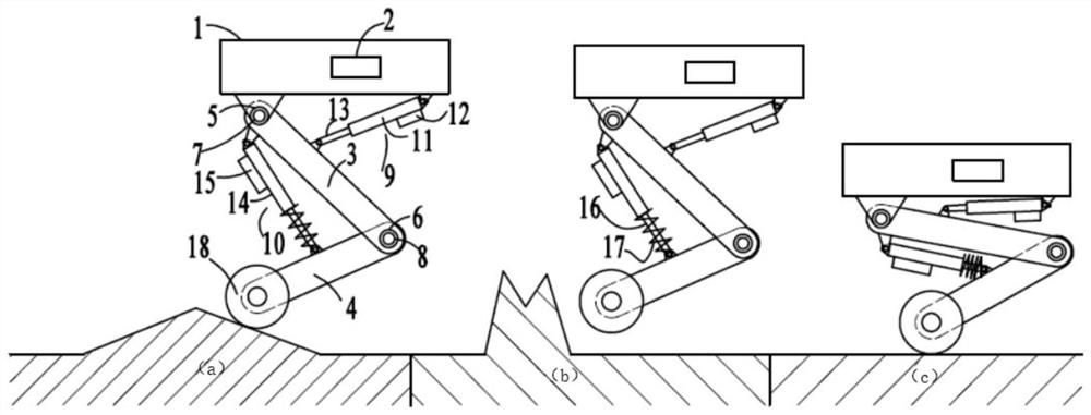
[0031] Such as Figure 1-5 As shown, it is a wheel-legged robot. The wheel-legged robot mainly includes a car body 1, a controller 2, a thigh 3, a calf 4, a hip revolving joint 5, and a knee revolving joint 6. The car body 1 and the thigh 3 are hinged to form a The hip revolving joint 5 and the hinged position of the thigh 3 and the shank 4 form the knee revolving joint 6 , and the shank 4 is connected to a wheel, which is controlled by a motor 18 to rotate. Wheel-legged robots may have two legs or three legs or four legs, figure 1 Only one leg is used for illustration in .

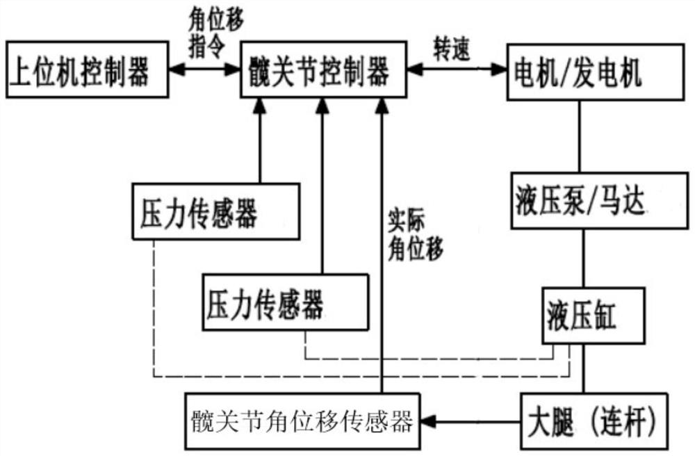
[0032] The hip joint angular displacement sen...


PUM


Abstract

The invention relates to the technical field of robots, in particular to a joint driving device of a wheel-legged robot, a control method and the wheel-legged robot, the joint driving device comprises a hip joint rotating actuator, a knee joint rotating actuator and a motor, the hip joint rotating actuator performs displacement closed-loop control extension/contraction through a hip joint electro-hydrostatic actuator, and the knee joint rotating actuator performs displacement closed-loop control extension/contraction through a knee joint electro-hydrostatic actuator. The knee joint rotation actuator performs displacement closed-loop control extension/contraction through the knee joint electro-hydrostatic actuator, the knee joint rotation actuator performs force closed-loop control vibration reduction through the knee joint electro-hydrostatic actuator, and the motor drives the wheels to rotate/stop through the controller. The wheel-legged robot aims to take wheel-type modal operation as a main mode and simple step-type modal movement as an auxiliary mode, and can well realize a vibration reduction function in a wheel-type mode and can well realize a leg stretching function in a step-type mode, so that the flexibility and functionality of the wheel-legged robot in an actual use process are considered.

Description

technical field [0001] The invention belongs to the technical field of robots, and in particular relates to a joint driving device, a control method and a wheel-leg robot of a wheel-leg robot. Background technique [0002] The wheel-legged robot refers to the addition of wheels at the end of the robot legs. This type of robot fully combines the advantages of wheels and legs. Passage in an unstructured environment. Compared with legged robots, it has faster traveling speed and energy efficiency in the road environment, so the research on wheel-legged robots has received more and more attention. [0003] At present, wheel-legged robots are generally developed on the basis of quadruped or bipedal robots. Driven by electric motors, its focus is to demonstrate wheel-legged robot control technology, rather than aiming at practical applications. Since the legged robot can only move in a step mode, in order to maintain balance during its movement, the legs generally have at least...

Claims


Application Information

Patent Timeline
IPC IPC(8): B62D57/028
Inventor 胡小东刘辉徐彬秦也辰周俊杰
Owner 北京理工大学重庆创新中心
Why Eureka
Try Eureka