Guniting slurry ground surface to underground conveying system

A conveying system and surface technology, applied in underground chambers, wellbore linings, shaft equipment, etc., can solve the problems of hidden traffic safety hazards, pollution of the surface and underground environment, high vehicle transportation costs, and reduce manual work and mechanized work. The effect of high degree and low maintenance cost

Pending Publication Date: 2022-04-12
安徽马钢矿业资源集团姑山矿业有限公司 +1
View PDF7 Cites 0 Cited by
  • Summary
  • Abstract
  • Description
  • Claims
  • Application Information

AI Technical Summary

Problems solved by technology

There are the following problems in this spraying material transportation method: 1. Economically, the transportation cost of automobile is very high, especially as the mining depth below the surface becomes deeper and deeper, the transportation cost also gradually increases
2. In terms of efficiency, the efficiency of automobile transportation is low and the supply of materials is not continuous, which increases the difficulty of construction for the section that needs to be formed at one time or the false bottom that is poured at one time
3. Safety, long-distance rail transportation, high roadway occupancy rate, potential traffic safety hazards, and easy vehicle accidents
4. In terms of environment, the dry spraying material is powdery particles, which will generate a lot of dust during transportation by car, polluting the surface and underground environment
[0003] With the continuous increase in the mining volume of metal underground mines, the shotcrete support materials required underground have also increased significantly; at the same time, the increase in mining depth has also increased transportation costs

Method used


Image

  • Guniting slurry ground surface to underground conveying system
  • Guniting slurry ground surface to underground conveying system
  • Guniting slurry ground surface to underground conveying system

Examples


Embodiment 1

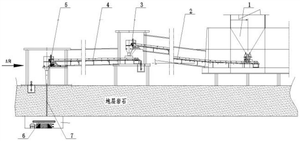
[0028] From Figure 1-4 It can be seen that a slurry surface of the present embodiment is a downhole transport system, including a stirring station 1, and the output of the stirring station 1 is connected to the first tape engine transport corridor 2, the first tape engine transport corridor 2 The output terminal is connected to the intermediate transfer station 3, and the output of the intermediate transfer station 3 is connected to the second tape engine transport corridor 4, and the output end of the second tape engine transport corridor 4 is connected to the lower body bucket device 5;

[0029] The output end of the lower body bucket device 5 is connected to the pore structure 7, and the output end of the echoleum structure 7 extends to the downhole and connected to the downhole transport station 6.

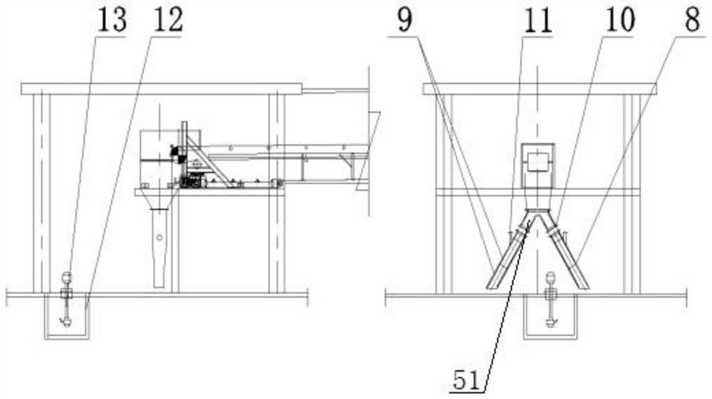
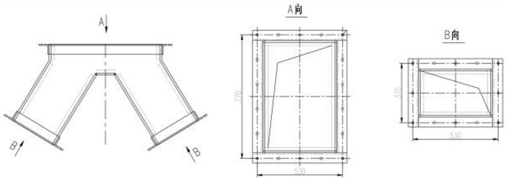
[0030] A double-port funnel 51 is provided at the lower body opening position of the lower body bucket device 5, and the output end of the double-port funnel 51 is connected to th...


PUM


Abstract

The invention discloses a system for conveying guniting slurry from the ground surface to the underground, and belongs to the technical field of guniting slurry conveying. The system comprises a mixing plant, the output end of the mixing plant is connected with a first sealing-tape machine transportation vestibule, the output end of the first sealing-tape machine transportation vestibule is connected with a middle transfer station, the output end of the middle transfer station is connected with a second sealing-tape machine transportation vestibule, and the output end of the second sealing-tape machine transportation vestibule is connected with a discharging machine hopper device; the output end of the discharging hopper device is connected with an ash sliding hole structure, the output end of the ash sliding hole structure extends to the underground and is connected with an underground conveying station, mechanical operation is adopted, manual operation is not needed for feeding, discharging and material cleaning, the manual operation amount is reduced, when the discharging hopper is blocked, a compressed air pipeline valve is directly opened, and the discharging hopper is not blocked. And the material recycling groove in the lower portion of the bottom plate is used for recycling leaked materials and then connected back to the mixing station to form circulating transportation, continuous feeding is achieved in the conveying process, and continuity and efficiency are high.

Description

Technical field [0001] The present invention relates to the field of slurry delivery technology, and more particularly to a slurry surface to a downhole delivery system. Background technique [0002] Concrete sprinkler is an important support material in the process of underground roadway. At present, during the underground mining process, the transport of the slurry from the surface to the downhole is mainly transferred from the car through the can cage to the downhole, or by the car through the surface ramps directly into the downhole harvest. This kind of injectment is in the case of the following problems: 2. In efficiency, car transportation efficiency is low and the feed is not continuous, and the difficulty of construction is increased for a broken section that requires one-time molding or a fake in turn. 3. Safety, long-distance rail transportation, high roadway occupancy rate, traffic safety hazard, easy to generate vehicle accidents. 4. Environmentally, dry sprinkler is...

Claims


Application Information

Patent Timeline
Patent Type & Authority Applications(China)
IPC IPC(8): E21D11/10
Inventor 陈轲周磊陈晨刘明宇印提军翟昊
Owner 安徽马钢矿业资源集团姑山矿业有限公司
Why Eureka
Try Eureka