Miniature diaphragm pump with precise flow adjusting device

A technology of flow regulating device and micro-diaphragm pump, which is applied in the direction of sampling device, pump with flexible working elements, etc. It can solve the problems of small effective measurement range, accelerated diaphragm corrosion and aging, and insensitivity to pressure changes, etc., to solve the problem of flow rate The effect of periodic fluctuations, prolonging the cleaning and maintenance cycle, and improving flow stability

Pending Publication Date: 2022-04-12
SHENZHEN AMAE INSTR
View PDF0 Cites 0 Cited by
  • Summary
  • Abstract
  • Description
  • Claims
  • Application Information

AI Technical Summary

Problems solved by technology

[0003] 2. The micro-diaphragm pumps currently on the market only have a single working chamber
The size of the sealed working chamber formed by the diaphragm and the pump head changes periodically. During the sampling test, the flow rate will have strong pulse fluctuations, the flow rate will change periodically, and the stability is poor. It is necessary to design a device for stabilizing the flow rate in the sampling equipment. Such as gas chambers, etc., these devices occupy a large volume, and can only play an auxiliary role in stabilizing the flow, and cannot fundamentally solve the problem of flow stability
Without an external flow stabilization device, existing micro-diaphragm pumps cannot meet high-precision measurement and sampling
[0004] 3. At present, the sampling diaphragm pumps on the market are external pressure measurement devices. The external pressure device needs to pass through a complex and long air circuit. The pressure takes time during the transmission process and there is loss, resulting in delayed response of the pressure measurement device, insensitive or unable Accurately measure pressure, especially in the case of small flow and weak pressure, and there are common problems such as signal distortion and difficulty in measurement
[0005] 4. At present, the flow range of sampling diaphragm pumps on the market is fixed, and the flow rate can only be changed by adjusting the motor speed. The consumption is high, and the diaphragm reciprocates rapidly, which not only damages the motor, but also greatly damages the life of the diaphragm pump. There are a large number of different types of complex acid-base substances in the sampling environment, the diaphragm moves rapidly, and the temperature rises, which will accelerate the corrosion and aging of the diaphragm. Resulting in greatly reduced service life of the pump
[0006] 5. The existing micro-diaphragm pump has only a single medium flow channel, regardless of the flow rate, it passes through the flow channel, and the size of the flow channel cannot be changed, which makes the pressure difference of flow measurement small and the pressure change Insensitive, in the case of high flow rate, the flow rate of the medium is high, the resistance increases exponentially, the power loss is large, and in the case of high flow rate, the medium has complex turbulence, which not only reduces the flow stability, but also reduces the turbulence. Accurate measurement of interference sensors
Therefore, the existing micro-diaphragm pump does not have a large flow range, limited application scenarios, low flow measurement multiples, small effective measurement range, and large measurement errors in some flow sections, which cannot satisfy multi-flow point sampling.

Method used


Image

  • Miniature diaphragm pump with precise flow adjusting device
  • Miniature diaphragm pump with precise flow adjusting device
  • Miniature diaphragm pump with precise flow adjusting device

Examples


Embodiment Construction

[0033] Embodiments of the present invention will now be described with reference to the drawings, in which like reference numerals represent like elements.

[0034]Wherein, in the description of the embodiments of the present disclosure, if the same or similar terms as “left”, “right”, “first”, “second” are involved, they are only used for the purpose of description, “left” or “right” It cannot be understood as indicating or implying the actual positional relationship. The features of "first" and "second" can expressly or implicitly indicate that they include one or more technical features that are identical or similar in structure and function, and cannot be understood as indicating Or imply the relationship of importance, primary and secondary.

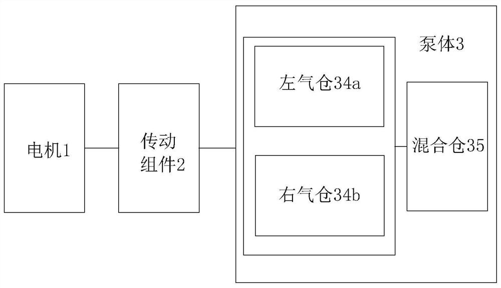
[0035] As mentioned above, such as figure 1 As shown, the embodiment of the present invention provides a micro-diaphragm pump with a precision flow regulating device, including: a motor 1 , a transmission assembly 2 and a pump body...


PUM


Abstract

The invention discloses a miniature diaphragm pump with a precise flow adjusting device. The miniature diaphragm pump comprises a motor, a transmission assembly and a pump body. The pump body comprises a middle shell, a left shell, a right shell, a left diaphragm piece, a right diaphragm piece, a left air bin, a right air bin and a mixing bin, the left diaphragm piece is arranged between the middle shell and the left shell, the right diaphragm piece is arranged between the middle shell and the right shell, the middle shell is provided with a working bin, the left shell is provided with the left air bin, and the right shell is provided with the right air bin; the transmission assembly, the left diaphragm piece and the right diaphragm piece are arranged in the working bin, the motor sequentially drives the left diaphragm piece and the right diaphragm piece to reciprocate through the transmission assembly, external gas is sequentially squeezed into the left gas bin and the right gas bin, and gas in the left gas bin and the right gas bin flows into the mixing bin and then is output to the flow adjusting device through the mixing bin. The flow adjusting device comprises an adjusting motor, a speed adjusting assembly and an adjusting device, and the adjusting device is used for adjusting the flow. The miniature diaphragm pump is stable in flow, wide in measuring range and high in measuring precision.

Description

technical field [0001] The invention relates to the technical field of micro-diaphragm pumps for air sampling, in particular to a micro-diaphragm pump with a precise flow regulating device with stable flow, wide measuring range and high measurement accuracy. Background technique [0002] 1. Diaphragm pump is a unique form of positive displacement pump. The rubber diaphragm inside the pump is driven by the motor to drive the eccentric to reciprocate, so that the size of the sealed working chamber formed by the diaphragm and the pump head changes periodically. The medium enters the working chamber through the inlet one-way valve when the working chamber becomes larger, and spits out the working chamber through the outlet one-way valve when the working chamber becomes smaller, and the pump reciprocates to complete the process of conveying the medium. Diaphragm pumps can be used to transport fluids with relatively unstable chemical properties. In the treatment of hazardous and c...

Claims


Application Information

Patent Timeline
IPC IPC(8): F04B45/047F04B39/12F04B39/10F04B49/22F04B49/20F04B49/06G01N1/24
Inventor 邱利明廖海祁杨康奋苏琴王旭张力
Owner SHENZHEN AMAE INSTR
Why Eureka
Try Eureka