
Non-contact particle size analyzer and application method thereof

A particle size analysis, non-contact technology, applied in the field of particle size analyzers, can solve problems such as inability to measure, instrument measurement is greatly affected by water vapor, complex mechanism, etc., to achieve ultra-high sensitivity and safety, and super anti-interference The effect of ability, strong mechanical structure

Pending Publication Date: 2022-04-12
杭州科灵威识精密仪器有限公司
View PDF0 Cites 0 Cited by
  • Summary
  • Abstract
  • Description
  • Claims
  • Application Information

AI Technical Summary

Problems solved by technology

[0007] At present, the existing technology for measuring particle concentration and particle size is the laser penetrating principle measurement method. The defects of the instrument of this principle are: 1. Since the light needs to be aimed, the flue in the use occasion should not have a large vibration, otherwise the light will 2. When light encounters particles in the direction of propagation, it will be scattered in all directions. In a specific direction, the intensity of light is related to the concentration of particles. The mechanism is complex and greatly affected by the measurement conditions; 3. Meter measurement It is relatively affected by water vapor, because the equipment is installed on the flange surface outside the valve at the root of the pipeline. If the lens of the instrument is affected by condensed water vapor, serious jumps will occur, and most of them will affect the measurement results; 4. Pollutants Attaching to the lens will block the light and affect the measurement, so regular maintenance is required, and the maintenance workload is relatively large; 5. The lens is polluted by particles for a long time, and the light source and photosensitive element drift seriously

Method used


Image

  • Non-contact particle size analyzer and application method thereof
  • Non-contact particle size analyzer and application method thereof
  • Non-contact particle size analyzer and application method thereof

Examples


Embodiment Construction

[0041] The present invention will be described in further detail below in conjunction with the accompanying drawings.

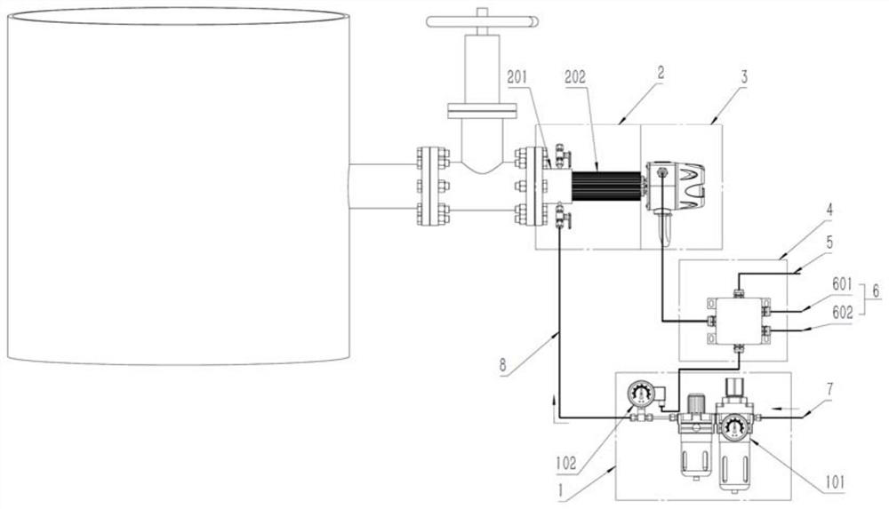
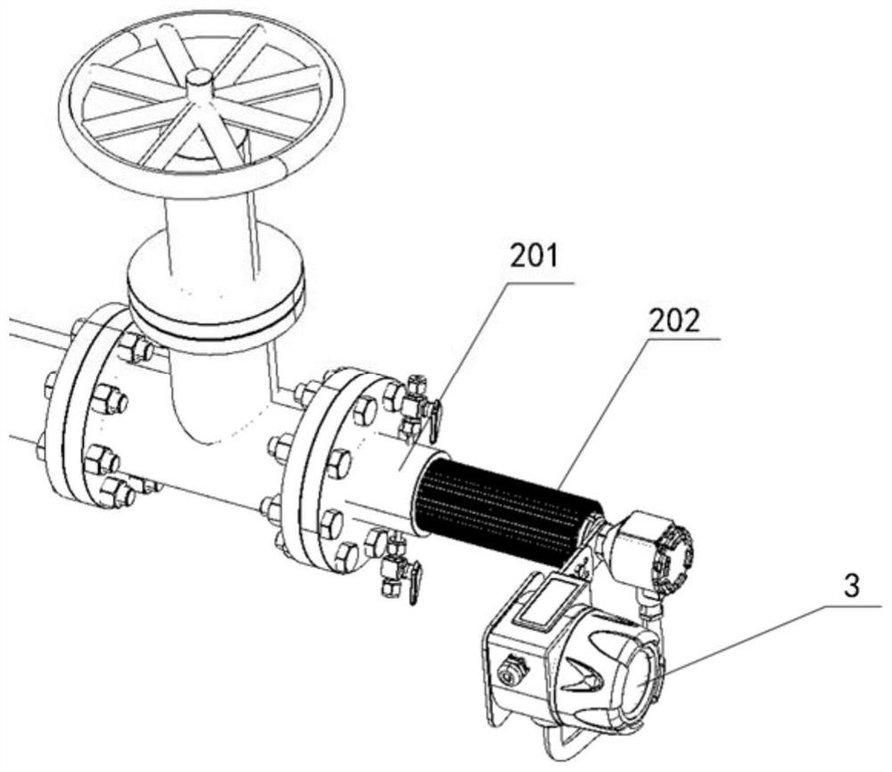
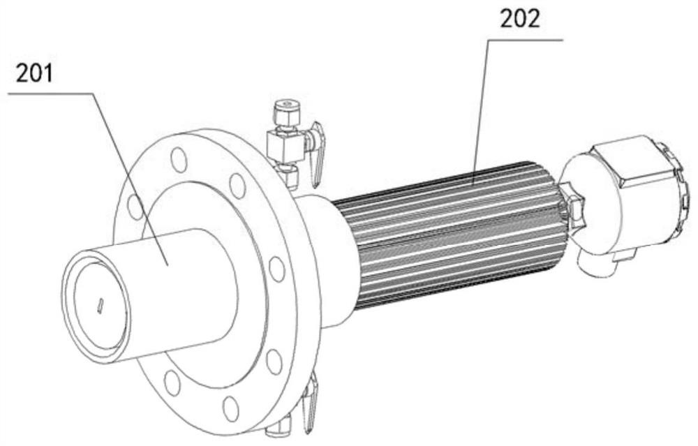
[0042] Such as figure 1 , figure 2 and image 3 As shown, a non-contact particle size analyzer includes a purging device 1, a signal acquisition device 2, a data analysis processing unit 3 and an electrical connection unit 4, and the signal acquisition device 2 includes a sensor 201 and a radiator 202, The purging device 1 is connected to the sensor 201 , the sensor 201 is connected to the data analysis and processing unit 3 , the data analysis and processing unit 3 is connected to the electrical connection unit 4 , and the electrical connection unit 4 is connected to the power cable 5 and the signal output cable 6 .

[0043] Further, the signal output cable 6 includes three analog 4-20mA output terminals 601 and one RS485 output terminal 602 .

[0044] Further, the sensor 201 is made of high-sensitivity electrostatic signal sensing material and is disc-s...


PUM


Abstract

The invention discloses a non-contact particle size analyzer and an application method thereof, the non-contact particle size analyzer comprises a purging device, a signal acquisition device, a data analysis processing unit and an electrical connection unit, the signal acquisition device comprises a sensor and a radiator, the purging device is connected to the sensor, and the data analysis processing unit is connected to the radiator. The sensor is connected with the data analysis processing unit, the data analysis processing unit is connected with the electrical connection unit, and the electrical connection unit is connected with the power cable and the signal output cable. Based on a particulate matter electrostatic induction measurement core technology of a fluid / statistical model and digital signal processing, the system has an ultra-wide dynamic range and ultra-strong anti-interference capability; under the condition that the measurement requirement is met, any part of the sensor does not need to extend into the valve, and online installation and online maintenance can be realized; the non-contact measurement is realized, the sensitivity and the safety are ultrahigh, and the process is not influenced under the condition that the measurement accuracy is ensured; the adaptability is high.

Description

technical field [0001] The invention relates to a particle size analyzer, in particular to a non-contact particle size analyzer and an application method thereof. Background technique [0002] The sensor of the non-contact particle size analyzer is a non-contact sensing device. It only needs to install the sensor on the online flange of the measured pipeline without inserting the flue. The depth is no more than the position of the valve plate of the gate valve, but not limited to this size), and an analytical instrument that can monitor the particle concentration and particle size in the pipeline. It is mainly used in chemical industry, iron and steel industry, coal industry, petrochemical industry, which is not easy to maintain or requires particle size measurement. For example, when the particle size analyzer fails, the equipment cannot be maintained under working conditions that cannot be shut down, or the relatively harsh working conditions such as high pressure, high t...

Claims


Application Information

Patent Timeline
Patent Type & Authority Applications(China)
IPC IPC(8): G01N15/02G01N15/06G01N15/08
Inventor 乔建飞张良
Owner 杭州科灵威识精密仪器有限公司
Learn More