
High and low orbit bistatic synthetic aperture radar frequency domain rapid imaging method

A synthetic aperture radar and fast frequency domain technology, applied in the field of radar, can solve the problems of inability to achieve precise focusing and large amount of computation, and achieve the effect of precise focusing and high precision

Active Publication Date: 2022-04-12
UNIV OF ELECTRONICS SCI & TECH OF CHINA
View PDF12 Cites 0 Cited by
  • Summary
  • Abstract
  • Description
  • Claims
  • Application Information

AI Technical Summary

Problems solved by technology

[0007] In order to solve the problem that the high and low orbit bistatic SAR frequency domain imaging method is limited by the unknown accurate spectrum and the existing bistatic SAR time domain imaging method has a large amount of calculation, so that it cannot achieve accurate focusing, the present invention proposes a high and low orbit bistatic synthesis Aperture radar frequency-domain rapid imaging method can effectively realize high-precision frequency-domain imaging of high- and low-orbit bistatic SAR in sliding spotlight mode

Method used


Image

  • High and low orbit bistatic synthetic aperture radar frequency domain rapid imaging method
  • High and low orbit bistatic synthetic aperture radar frequency domain rapid imaging method
  • High and low orbit bistatic synthetic aperture radar frequency domain rapid imaging method

Examples


Embodiment 1

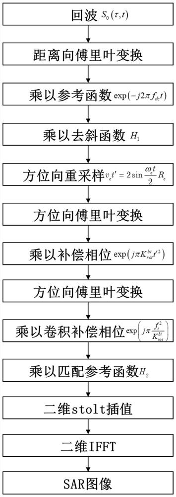
[0060] Such as figure 1 Shown, method of the present invention comprises the following steps:

[0061] Step 1: Generate the high and low orbit trajectory according to the set high and low orbit satellite orbit parameters, and generate the echo signal S 0 (τ,t);

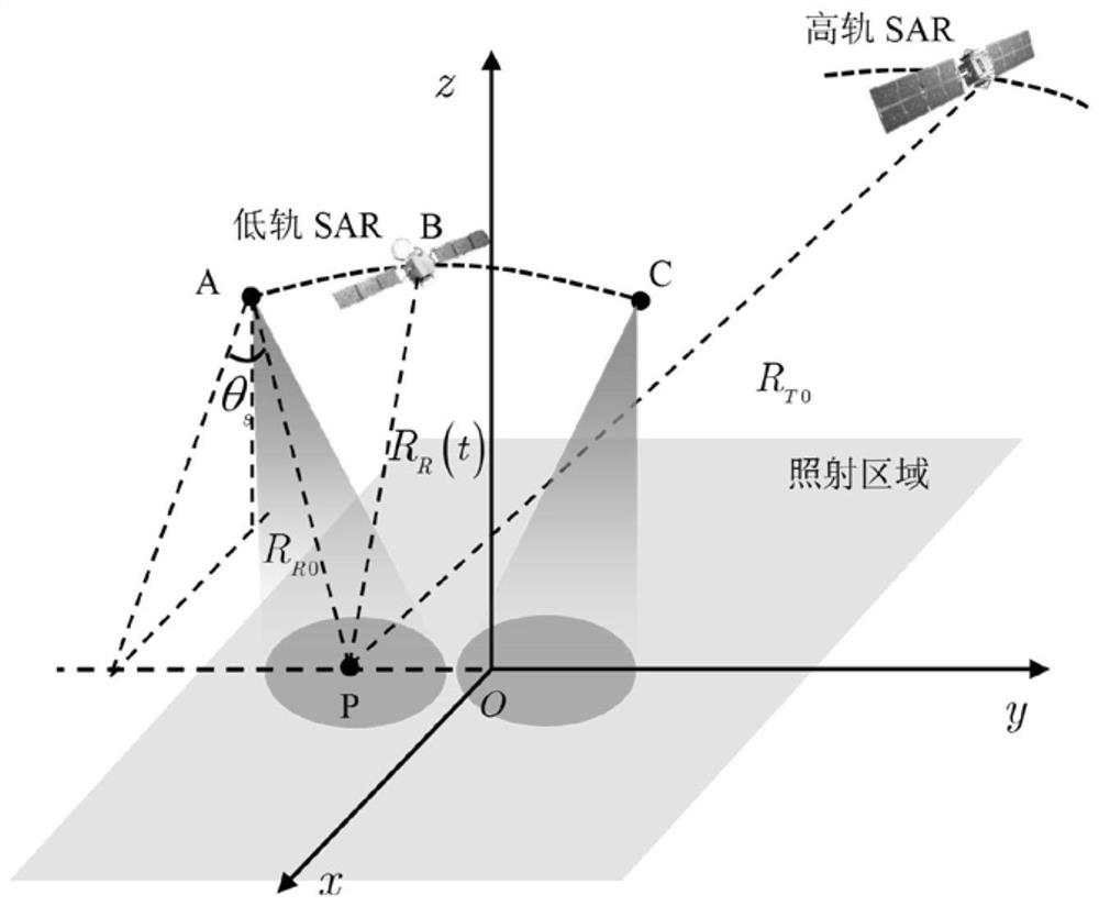
[0062] Convert the motion parameters of the high and low orbit platform into the target imaging coordinate system. The xOy plane is tangent to the surface of the earth. The tangent point is the center point O of the imaging scene, which is also the origin of the coordinates. The axis is the velocity direction of the low-orbit SAR satellite at zero azimuth, and the x-axis is perpendicular to the y-axis, satisfying the right-hand rule.

[0063] Record the azimuth time vector as: t={-PRI·N a / 2,-PRI (N a / 2-1),…,PRI (N a / 2-1)} T , PRI is the pulse repetition interval, N a is the number of target echo azimuth points.

[0064] Write the distance time vector as: τ={-1 / Fs N r / 2,-1 / Fs (N r / 2-1),…,1 / Fs (N r / 2-1)...

Embodiment 2

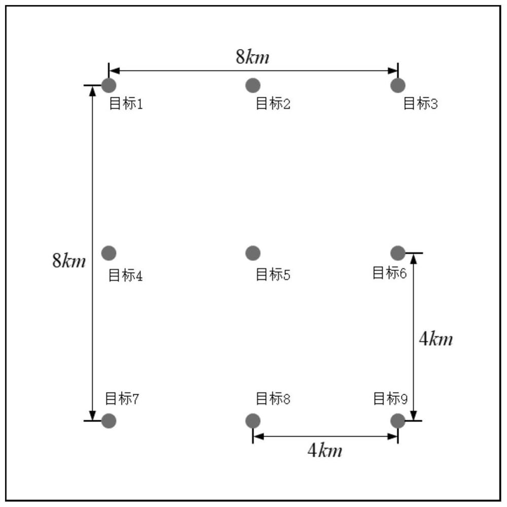
[0184] The target scenario based on this embodiment is as follows image 3 As shown, the simulation parameters used are shown in Table 1, Figure 4 for image 3 The results of imaging with 9 point targets in the image.

[0185] Table 1 Bistatic SAR simulation parameters

[0186]

[0187] Figure 4 is true image 3 The imaging results of 9 point targets in the Figure 4 It can be seen from the figure that the method provided by the present invention can well realize high and low orbit bistatic SAR imaging processing, and can realize precise focusing on high and low orbit bistatic SAR echoes.


PUM


Abstract

The invention discloses a high and low orbit bistatic synthetic aperture radar frequency domain fast imaging method, which is applied to the technical field of radars and aims at solving the problems that the high and low orbit bistatic synthetic aperture radar frequency domain imaging method is limited by unknown accurate frequency spectrum and the existing bistatic synthetic aperture radar time domain imaging method is large in calculation amount so that accurate focusing cannot be realized. According to the invention, a high-precision high-low orbit bistatic SAR distance model based on a'non-stop walking stop 'hypothesis is constructed, and the distance model is converted into a simple form beneficial to solving a two-dimensional frequency spectrum by using an azimuth resampling technology, so that an azimuth pre-filtering processing method of the high-low orbit bistatic SAR is provided; the problem of azimuth spectrum aliasing caused by space-variant of an azimuth centroid in a low-orbit SAR sliding bunching mode is solved, and finally accurate focusing is carried out on echo data through an improved omega-K imaging method.

Description

technical field [0001] The invention belongs to the field of radar technology, in particular to a synthetic aperture radar imaging technology. Background technique [0002] Synthetic Aperture Radar (SAR) can achieve all-day and all-weather imaging observation capabilities, and is playing an increasingly important role in terrain mapping, resource surveying, ocean current and hydrological observation, disaster monitoring, vegetation analysis, military reconnaissance and other fields role. Compared with single-base SAR, bistatic SAR has the advantages of strong concealment, strong anti-interference, and high survivability due to its configuration characteristics of sending and receiving. It can realize light weight, miniaturization, low cost and diverse And it has all-round imaging capabilities of front view, side view and rear view. [0003] The bistatic SAR of the high and low orbit configuration, on the basis of the advantages of the conventional bistatic SAR, gives full ...

Claims


Application Information

Patent Timeline
Patent Type & Authority Applications(China)
IPC IPC(8): G01S13/90
Inventor 孙稚超陈天夫任航安洪阳武俊杰黄钰林杨建宇
Owner UNIV OF ELECTRONICS SCI & TECH OF CHINA
Learn More