
High resolution imaging system and method for near-earth target large field of view

A high-resolution, imaging system technology, applied in the field of optical measurement, which can solve the problems of complex optical system design, difficulty in meeting actual task requirements, and reduced detection capability.

Active Publication Date: 2022-04-12
NO 63921 UNIT OF PLA
View PDF9 Cites 0 Cited by
  • Summary
  • Abstract
  • Description
  • Claims
  • Application Information

AI Technical Summary

Problems solved by technology

In order to ensure the coverage of the system on the object space, there are usually two ways: the first is to take the required minimum field of view of the object space as the primary input condition in the design process, by reducing the focal length of the optical system, reducing the detection ability, reducing the The target image resolution is used to meet the requirements of the field of view. This method is most commonly used in the shooting range because of its low cost and strong operability. However, when the two indicators of detection capability and field of view are irreconcilable, the system cannot meet the actual task. need
And when the demand for the field of view of the object is too large, the design of the optical system may be too complicated, and it may even be impossible to achieve
The second method is to use multiple area array CCD devices to splice and expand the field of view, but this method is complex and inconvenient to operate in the field, and the cost is high

Method used


Image

  • High resolution imaging system and method for near-earth target large field of view
  • High resolution imaging system and method for near-earth target large field of view
  • High resolution imaging system and method for near-earth target large field of view

Examples


Embodiment Construction

[0044] The present invention will be further described in detail below through specific embodiments in conjunction with the accompanying drawings. Wherein, similar elements in different implementations adopt associated similar element numbers. In the following implementation manners, many details are described for better understanding of the present application. However, those skilled in the art can readily recognize that some of the features can be omitted in different situations, or can be replaced by other elements, materials, and methods. In some cases, some operations related to the application are not shown or described in the description, this is to avoid the core part of the application being overwhelmed by too many descriptions, and for those skilled in the art, it is necessary to describe these operations in detail Relevant operations are not necessary, and they can fully understand the relevant operations according to the description in the specification and genera...


PUM

PropertyMeasurementUnit
Rotation angleaaaaaaaaaa

Abstract

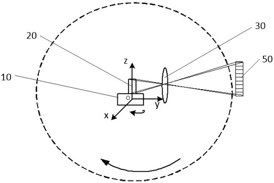
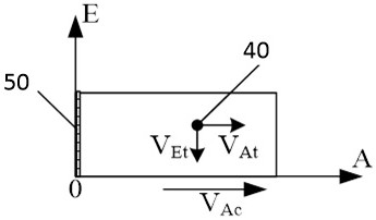
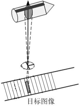
A high resolution imaging system and method for a near-earth target large field of view utilizes a linear array image sensor having a first pixel direction with more pixels covering an object field of view in a vertical direction and a second pixel direction with less pixels covering the object field of view in a horizontal direction, and the horizontal view field is expanded in the second pixel direction through rotation of the rotary scanning mechanism, so that coverage of any horizontal view field angle of 0-360 degrees is realized. The method comprises the following steps: determining an overlapping region among a plurality of target image frames obtained by single scanning, eliminating the overlapping region in the process of splicing each target image frame according to a time sequence to obtain a frame of high-resolution target image, and scanning for multiple times to obtain the high-resolution image of the target. The device is simple in structure, convenient to operate and low in cost, can obtain a high-resolution target image while achieving coverage of any view field within 0-360 degrees, and has a great application prospect in the field of shooting range live image obtaining.

Description

technical field [0001] The invention relates to the technical field of optical measurement, in particular to a high-resolution imaging system and method for a large field of view of a near-earth target. Background technique [0002] The live image of the target can provide real-time and intuitive task data for the on-site command personnel, and provide first-hand information for judging the success or failure of the task. Obtaining live images of targets has a wide range of application requirements in the shooting range. With the development of technology, there are currently higher requirements for the acquired live images. It is not only required to be able to obtain target images, especially for some key feature points, but also to be able to obtain high-resolution targets that can clearly see the detailed information of the target. image. [0003] At present, the measurement systems used in shooting ranges for live image acquisition of near-Earth targets all use area a...

Claims


Application Information

Patent Timeline
IPC IPC(8): G02B26/10
Inventor 高昕李希宇胡蕾雷呈强郑东昊唐嘉林燕
Owner NO 63921 UNIT OF PLA
Features
  • Generate Ideas
  • Intellectual Property
  • Life Sciences
  • Materials
  • Tech Scout
  • Unparalleled Data Quality
  • Higher Quality Content
  • 60% Fewer Hallucinations
Learn More