
Coating mixing device for water pump production line and mixing method thereof

A technology of mixing device and production line, applied in the field of paint mixing device for pump production line, can solve the problems of paint heating, affecting the cleaning effect of the inner wall of the mixing tank, and high paint viscosity, and achieving the effect of cleaning

Inactive Publication Date: 2022-04-15
闫文所
View PDF0 Cites 1 Cited by
  • Summary
  • Abstract
  • Description
  • Claims
  • Application Information

AI Technical Summary

Problems solved by technology

[0004] The purpose of the present invention is to solve the problem that in the prior art, due to the inability to heat the paint poured into the mixing tank, the viscosity of the paint is high when mixed, which affects the mixing effect of the paint, and when cleaning the inner wall of the mixing tank , because it is cleaned by traditional cold water washing, which reduces the activity of paint molecules attached to the inner wall of the mixing tank, thereby affecting the cleaning effect of the inner wall of the mixing tank, and proposes a paint mixing device for a water pump production line and its mixing method

Method used


Image

  • Coating mixing device for water pump production line and mixing method thereof
  • Coating mixing device for water pump production line and mixing method thereof
  • Coating mixing device for water pump production line and mixing method thereof

Examples


Embodiment 1

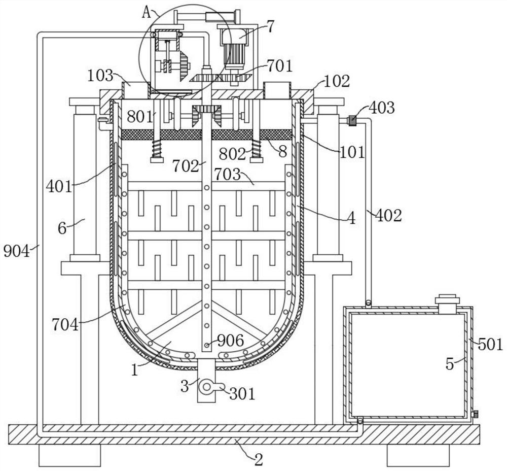
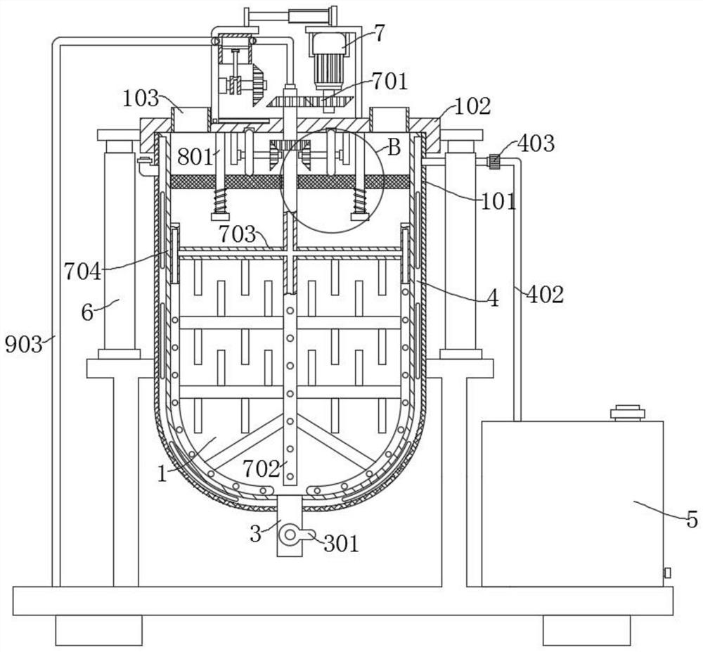
[0034] refer to Figure 1-5 , a paint mixing device for a water pump production line, including a support base 2, a mixing tank 1 is arranged on the support base 2, and a mixing assembly arranged in the mixing tank 1 for mixing the paint, and the top of the mixing tank 1 is provided with The tank cover 102, and the feed port 103 arranged on the tank cover 102; the scraper 704, arranged on the mixing assembly, and the scraper 704, and the mixing assembly are all provided with water nozzles 906; the water storage tank 5, arranged on the support seat 2, the mixing tank 1 and the water storage tank 5 are all provided with heating and heat preservation components, which are convenient for heating and heat preservation of the paint added to the mixing tank 1 and the water in the water storage tank 5 through the heating and heat preservation components; the piston assembly 903 is arranged on Above the tank cover 102; one end of the conduit 904 is connected to the water storage tank 5...

Embodiment 2

[0047] refer to figure 1 , figure 2 , a paint mixing device for a water pump production line, which is basically the same as in Example 1, furthermore, the outer wall of the mixing tank 1 is provided with an insulating layer 101; through the insulating layer 101, the loss of heat in the mixing tank 1 can be reduced, and Avoid burns when the staff touches the outer wall of the mixing tank 1 .

Embodiment 3

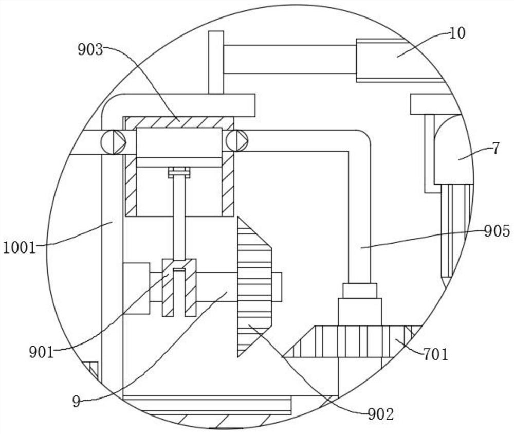
[0049] refer to Figure 1-Figure 3 , a paint mixing device for a water pump production line, which is basically the same as that of Embodiment 1, and furthermore, the drive assembly that drives the piston assembly 903 to move to supply water to the water nozzle 906 includes an electric telescopic rod 10, and the electric telescopic rod 10 is installed on the On the tank cover 102, the output end of the electric telescopic rod 10 is provided with a support plate 1001, the piston assembly 903 is arranged on the support plate 1001, the support plate 1001 is equipped with a rotating shaft 3 9, and a crankshaft 901 and a bevel gear 902 are arranged on the rotating shaft 3 9, The crankshaft 901 is rotatably connected to the piston assembly 903 , and the bevel gear 902 is driven by the electric telescopic rod 10 to engage or separate from the first transmission group 701 .

[0050] After the paint is mixed and discharged out of the mixing tank 1 through the discharge pipe 3, the elec...


PUM


Abstract

The invention discloses a coating mixing device for a water pump production line and a mixing method thereof, and belongs to the technical field of water pump production. The paint mixing device for the water pump production line comprises a supporting seat, a mixing tank is arranged on the supporting seat, and the paint mixing device further comprises a mixing assembly arranged in the mixing tank and used for mixing paint; according to the paint mixing device, water in the first sealing cavity is heated, so that the heated water can heat paint in the mixing tank, and the situation that the viscosity of the paint is high in the stirring process in cold weather, and the mixing effect of the paint is affected is prevented; water vapor is generated in the water heating process and enters a second sealing cavity through a pipeline to heat water in a water storage tank, so that when hot water cleans the inner wall of the mixing tank subsequently, the activity of molecules in a coating is improved, and then the cleaning effect on the inner wall of the mixing tank is improved; and the coating is screened through the screen before being mixed, so that the quality of the mixed coating is improved.

Description

technical field [0001] The invention relates to the technical field of water pump production, in particular to a paint mixing device for a water pump production line and a mixing method thereof. Background technique [0002] A water pump is a machine that transports or pressurizes a liquid. It transmits the mechanical energy of the prime mover or other external energy to the liquid to increase the energy of the liquid. It is mainly used to transport liquids including water, oil, acid and alkali, emulsions, and suspoemulsions. and liquid metal etc. [0003] At present, after the production of the water pump casing is completed, a layer of frosted anti-rust coating will be sprayed on the outside of the water pump casing. Therefore, a paint mixing device will be used to mix the paint before spraying. However, the current existing paint mixing device, in When mixing paint in cold weather, since the paint poured into the mixing tank cannot be heated, the viscosity of the paint i...

Claims


Application Information

Patent Timeline
IPC IPC(8): B01F27/90B01F27/191B01F27/112B01F23/70B01F35/11B01F35/12B01F35/92B01F101/30
Inventor 闫文所
Owner 闫文所
Learn More