
Energy storage device for boiler waste heat recovery

A technology of energy storage device and boiler waste heat, applied in boiler cleaning device, boiler support/positioning device, steam boiler, etc., can solve the problems of difficult boiler waste heat recovery, large fuel consumption, waste of resources, etc., and achieve good sealing effect, volume The effect of reducing and increasing the temperature difference

Pending Publication Date: 2022-04-15
山东盛合电力工程设计有限公司
View PDF0 Cites 1 Cited by
  • Summary
  • Abstract
  • Description
  • Claims
  • Application Information

AI Technical Summary

Problems solved by technology

[0002] During the use of boilers in iron and steel enterprises, a large amount of fuel is usually consumed, accompanied by a large amount of flue gas, and the exhaust gas temperature of the boilers used in iron and steel enterprises is also very high. In the past, these high-temperature flue gases were directly discharged to the atmosphere , resulting in a huge waste of resources. At present, in order to save energy, many technologies have been produced to recover the waste heat of this high-temperature flue gas. In the existing technology, the waste heat recovery and utilization facilities usually used are heat exchangers, but Because the flue gas temperature fluctuates violently and the dust content is large, the ordinary water tube waste heat boiler is difficult to be used in the waste heat recovery of boilers used in iron and steel enterprises.

Method used


Image

  • Energy storage device for boiler waste heat recovery
  • Energy storage device for boiler waste heat recovery
  • Energy storage device for boiler waste heat recovery

Examples


Embodiment Construction

[0026] In order to illustrate the technical features of the solution more clearly, the solution will be described below through specific implementation modes.

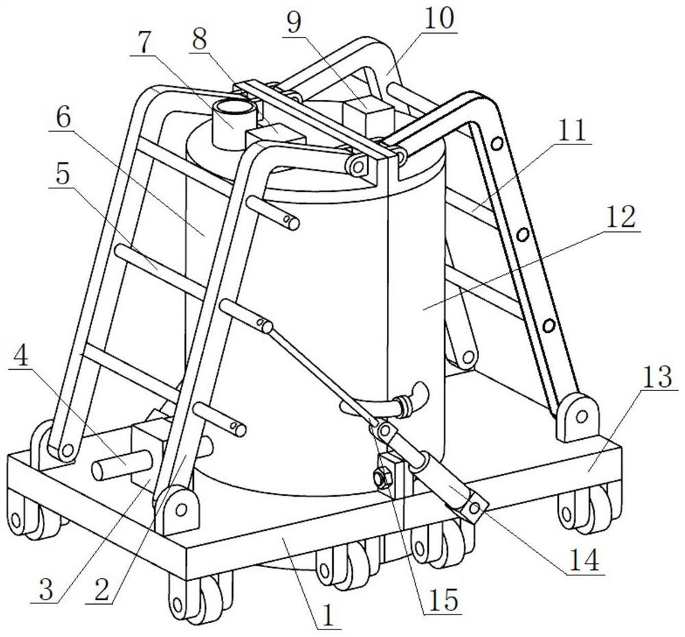
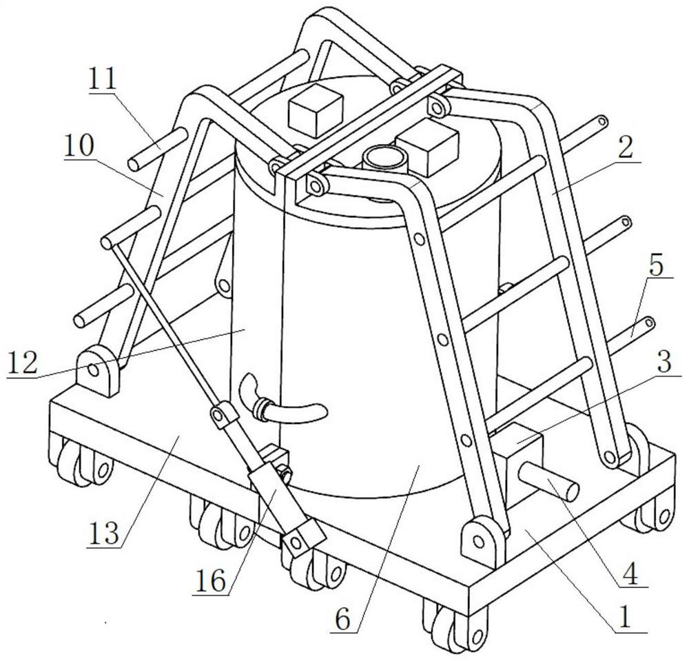
[0027] see figure 1 , figure 2 and Figure 4 , an energy storage device for recovery of boiler waste heat, comprising two closed structure 1 and closed mechanism 2 which can be connected to each other, and forms a closed space, a boiler is arranged in the closed space, a thermoelectric power generation component is arranged in the closed space, and the closed structure 1 A steam component is also arranged in the second closed structure and the closed structure respectively.

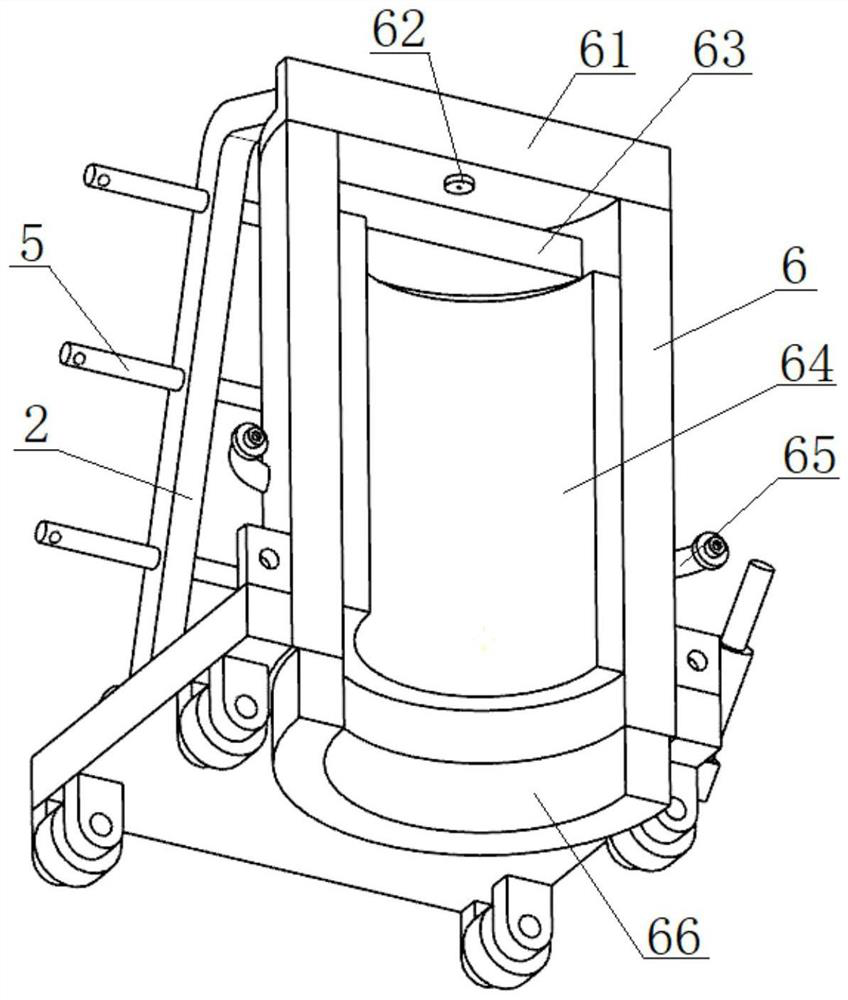
[0028] see image 3 The closed structure-includes a bottom plate-1 arranged horizontally, an arc-shaped cover-6 vertically arranged on the bottom plate-1, an upper air bag-64 arranged inside the arc-shaped cover-6, and an upper airbag-64 arranged on the top end of the arc-shaped cover-6 The top cover one 61, the bottom end surface of the bott...


PUM


Abstract

The invention provides an energy storage device for boiler waste heat recovery, which comprises a closed structure I and a closed structure II which can be butted with each other and form a closed space, a boiler is arranged in the closed space, a thermoelectric power generation assembly is arranged in the closed space, and steam assemblies are respectively arranged in the closed structure I and the closed structure II. The first sealing structure comprises a first horizontally-arranged bottom plate, a first arc-shaped cover vertically arranged on the first bottom plate, a first upper air bag arranged on the inner side of the first arc-shaped cover and a first top cover arranged at the top end of the first arc-shaped cover, and a first lower air bag is further arranged on the bottom end face of the first bottom plate and arranged below the first upper air bag. The first lower air bag is in separable contact with the ground. According to the energy storage device for boiler waste heat recovery, the technical problem of how to efficiently recycle boiler waste heat is solved, heat energy in the boiler is converted into electric energy, and energy loss is greatly reduced.

Description

technical field [0001] The invention belongs to the technical field of boiler equipment, and in particular relates to an energy storage device for boiler waste heat recovery. Background technique [0002] During the use of boilers in iron and steel enterprises, a large amount of fuel is usually consumed, accompanied by a large amount of flue gas, and the exhaust gas temperature of the boilers used in iron and steel enterprises is also very high. In the past, these high-temperature flue gases were directly discharged to the atmosphere , resulting in a huge waste of resources. At present, in order to save energy, many technologies have been produced to recover the waste heat of this high-temperature flue gas. In the existing technology, the waste heat recovery and utilization facilities usually used are heat exchangers, but Because the flue gas temperature fluctuates sharply and the dust content is large, the ordinary water tube waste heat boiler is difficult to be used in the...

Claims


Application Information

Patent Timeline
Patent Type & Authority Applications(China)
IPC IPC(8): F22B33/18F22B37/24F22B37/36F22B37/54H02N11/00
Inventor 季海龙许悦悦鞠欢苗西磊
Owner 山东盛合电力工程设计有限公司
Learn More