Array substrate, liquid crystal display panel and display device

An array substrate and electrode technology, applied in the field of virtual reality, can solve the problem of low transmittance of comb-shaped electrodes, and achieve the effects of reducing ineffective electric field components, reducing dark domains, and improving transmittance

Pending Publication Date: 2022-04-15
WUHAN CHINA STAR OPTOELECTRONICS TECH CO LTD
0 Cites 0 Cited by

AI-Extracted Technical Summary

Problems solved by technology

[0002] The development of virtual reality (VR) technology in display technology is relatively competitive. The display panel of VR display device has higher response speed and higher resolution (generally around...

Method used

Because response time can increase and decrease along with electrode inclination angle and penetration rate increases with electrode inclination angle and first rises and then descends, consider the relationship between response time and penetration rate and electrode inclination angle, the application will be The value range of the above-mentioned first inclination angle is set between 3°-35°, which can reduce the invalid electric field component and the electric field disorder area while taking into account the corresponding time, and reduce the area of ​​the dark area of ​​the display, thereby improving the transmittance.
The array substrate, liquid crystal display panel and display device provided by the application, 1) the shape of the first electrode is designed to: have a first waist (consisting of the first side wall, the second side wall and the first bottom wall) and the second waist (consisting of the third side wall, the fourth side wall and the second bottom wall), and the shortest distance from the first waist to the second waist is less than the distance between the first side wall and the second The distance from one end of the side wall to the end of the third side wall away from the fourth side wall is less than the distance from the end of the second side wall far away from the first side wall to the end of the fourth side wall far away from the first side wall The distance between one end of the three side walls can be used to obtain a fish-like electrode. By changing the shape of the first electrode, the ineffective electric field component and the electric field disorder area can be reduced, thereby reducing the area of ​​the dark area of ​​the display, thereby improving the penetration while taking into account the response time. transmittance. 2) The angle between the end of the first side wall close to the second side wall and the end of the third side wall close to the fourth side wall and the first direction is greater than 0° , making the first waist part and the second waist part asymmetrical, not only can increase the selectable range of the inclination angle of the first electrode, but also can avoid the mutual interfer...

Abstract

The invention provides an array substrate, a liquid crystal display panel and a display device, the array substrate comprises a driving circuit layer and a first electrode located on the driving circuit layer, and the driving circuit layer comprises a scanning line and a data line; the extension direction of the scanning lines is defined as a first direction, and the extension direction of the data lines is defined as a second direction; the first electrode comprises an entity part, and the entity part comprises a first side wall, a second side wall and a first bottom wall; one ends of the first side wall and the second side wall are connected through the first bottom wall; and a third side wall, a fourth side wall and a second bottom wall. One end of the third side wall is connected with one end of the fourth side wall through the second bottom wall; the shortest distance from the first bottom wall to the second bottom wall is defined as d1, the distance from one end, far away from the second side wall, of the first side wall to one end, far away from the fourth side wall, of the third side wall is defined as d2, the distance from one end, far away from the first side wall, of the second side wall to one end, far away from the third side wall, of the fourth side wall is defined as d3, and d1lt is defined; d1, d2 and d1lt; and d3.

Application Domain

Non-linear optics

Technology Topic

PhysicsLiquid-crystal display +5

Image

  • Array substrate, liquid crystal display panel and display device
  • Array substrate, liquid crystal display panel and display device
  • Array substrate, liquid crystal display panel and display device

Examples

  • Experimental program(1)

Example Embodiment

[0055] The technical solutions in the present application embodiment will be described in conjunction with the drawings in the present application embodiment. Obviously, the described embodiments are merely the embodiments of the present invention, not all of the embodiments. Based on the embodiments in the present application, those skilled in the art will belong to the scope of this application without all other embodiments obtained without creative labor.
[0056] In the description of the present application, it is to be understood that the orientation or positional relationship indicated by the term "upper", "lower", etc. is based on the orientation or positional relationship shown in the drawings, is only for ease of describing the present application and simplified description. Instead of indicating or implying that the device or component must have a specific orientation, constructing and operating in a particular direction, so it is not understood to limit the limitation of the present application. Moreover, the term "first", "second" is used only for the purpose of describing, and cannot be understood as an indication or implies a relative importance or implicitting the number of indicated techniques. Thus, features of "first", "second" may be indicated or implicitly including one or more of the features. In the description of the present application, the meaning of "multiple" is two or more, unless otherwise specifically defined.
[0057] The present application can repeat the reference numerals and / or reference letters in different implementations, which is for simplified and clear purposes, which itself does not indicate the relationship between the various embodiments and / or settings.
[0058] The array substrate, liquid crystal display panel and display device provided herein will be described in detail below in conjunction with specific embodiments and drawings.
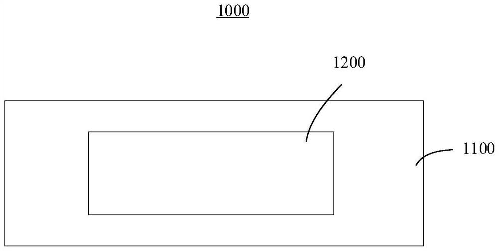
[0059] See figure 1 The present application also provides a display device 1000, the display device 1000 including the liquid crystal display panel 1200 and the main body portion 1100, the liquid crystal display panel 1200 disposed on the main body portion 1100.
[0060] In an alternative embodiment of the present application, the display device 1000 is a virtual reality (VR) display device. Of course, in other embodiments, the type of the display device 1000 is not limited to the VR display device.
[0061] Wherein, the liquid crystal display panel 1200 includes an array substrate, a color film substrate, and a liquid crystal, the liquid crystal located between the array substrate and the color film substrate.
[0062] The display mode of the liquid crystal display panel 1200 can be one of the FFS mode, IPS mode, and VA mode.
[0063] In the preferred embodiment of the present application, the display mode of the liquid crystal display panel 1200 is an FFS mode. Specifically, the array substrate includes a substrate, a driving circuit layer disposed above the substrate and a first electrode and a second electrode formed on the driving circuit layer, the second electrode located at the drive circuit layer. On the upper, the first electrode is opposed to the second electrode position, and the first electrode is spaced between the second electrodes by an insulating layer. The first electrode is located above the second electrode, i.e., the first electrode is a top electrode (TOP electrode), the second electrode as a bottom electrode (Bottom electrode).
[0064] When the first electrode is a common electrode, the second electrode is electrically connected to the drive circuit layer. When the first electrode is a pixel electrode, the first electrode is electrically connected to the drive circuit layer.
[0065] In other embodiments, when the first electrode is a pixel electrode, the second electrode is a common electrode, and the second electrode may also be disposed within the drive circuit layer.
[0066] In another alternative embodiment of the present application, the display mode of the liquid crystal display panel 1200 is an IPS mode, and the first electrode and the second electrode of the array substrate are provided on the drive circuit layer and Located on the same layer.
[0067] In another alternative embodiment of the present application, the display mode of the liquid crystal display panel is a VA mode, and the first electrode of the array substrate is a pixel electrode and is formed on the drive circuit layer, the second electrode is located. The color film substrate is within the substrate.
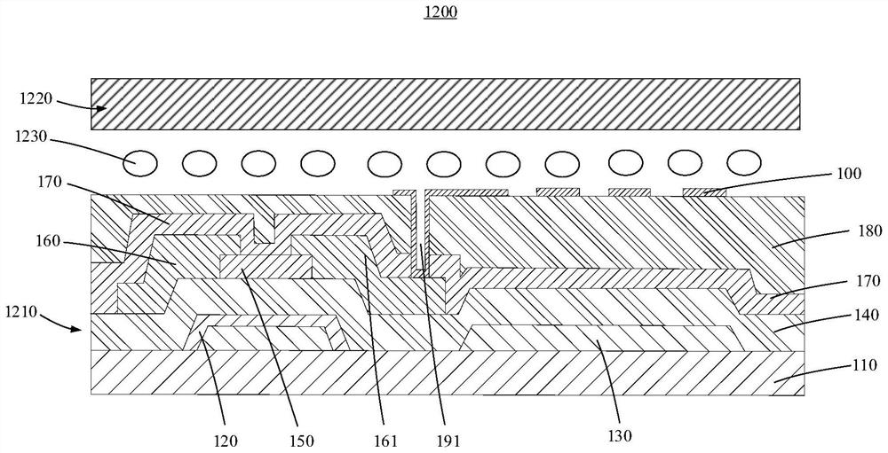
[0068] Specifically, see figure 2 , Below figure 2 The structure of the liquid crystal display panel 1200 shown is an example, and the structure of the liquid crystal display panel 1200 and the array substrate 1210 is briefly described.
[0069] exist figure 2 In the liquid crystal display panel 1200, the liquid crystal display panel 1200 includes an array substrate 1210, a color film substrate 1220, and a liquid crystal 1230, the liquid crystal 1230 located between the array substrate 1210 and the color film substrate 1220.
[0070] exist figure 2 In the display mode of the liquid crystal display panel 1200, the display mode of the liquid crystal display panel 1200, the array substrate 1210 includes a substrate 110, a driving circuit layer located above the substrate 110, formed in the driving circuit layer, 100 electrode 100 And the second electrode 130 formed in the drive circuit layer, the first electrode 100 is opposed to the second electrode 130, the first electrode 100 is located above the second electrode 130, the first The electrode 100 is insulated between the second electrode 130. In the present embodiment, the first electrode 100 is a pixel electrode.
[0071] The drive circuit layer includes a plurality of drive transistors, each of which includes a gate 120 formed on the substrate 110, formed on the substrate 110 and covers a gate of the gate electrode 120. The polar insulating layer 140 is formed on the gate insulating layer 140 and an active layer 150 opposite to the gate 120 position, which is formed at the gate insulating layer 140 and electrically connected to the active layer 150, respectively. The source or drain 160 is formed on the gate insulating layer 140 and covers the source drain 160 and the passivation layer 170 of the active layer 150 from the source drain 160 and is formed. The flat layer 180 on the passivation layer 170. The second electrode 130 is formed on the substrate 110 and is covered by the gate insulating layer 140, the first electrode 100 being formed on the flat layer 180 and is opposite to the second electrode 130. The first electrode 100 is electrically connected to the source drain 160, in the present embodiment, the first electrode 100 is electrically connected to the source drain 160 via an overhead 191.
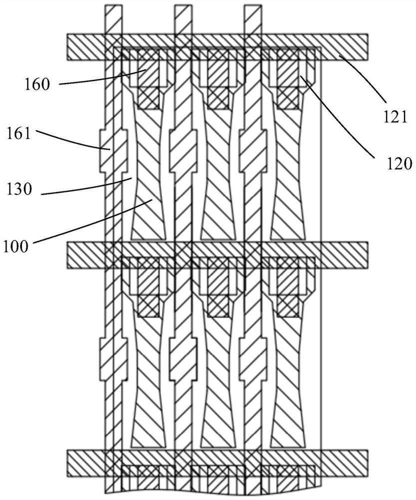
[0072] See image 3 In this embodiment, the array substrate 1210 further includes a plurality of scan lines 121 and a plurality of data lines 161, the scan line 121, is disposed in the same layer of the gate electrode 120 and is electrically connected to the gate 120. The data line 161 is provided with the source drain 160 and is electrically connected to the source drain 160. The scan line 121 is configured to provide a scan signal for the drive transistor, which is configured to provide a data signal for the drive transistor. The plurality of scan lines 151 and the plurality of data lines 161 are arranged, and the plurality of scan lines 151 are arranged along the line, and the plurality of data lines 161 are set along column, and the plurality of scan lines 151 and the plurality of data lines 161 constitute a plurality of pixel units. The pixel unit has at least one of the driving transistors, one of the first electrodes 100 and one of the second electrodes 130, the first electrode 100 being a pixel electrode, the second electrode 130 being a common electrode. The first electrode 100 is opposite to the second electrode 130 to form an electric field that drives the liquid crystal 1230.
[0073] Of course, in other embodiments, the structure of the array substrate 1210 is not limited to the structure as described above.
[0074] In the present embodiment, the first electrode 100 is a fish shape, the second electrode 130 being a sheet-like electrode, and one of the common electrodes may correspond to one or more pixel electrodes.
[0075] Define the extension direction of the scanning line 121 as the first direction Y1, the extending direction of the data line 161 is the second direction Y2.
[0076] See Figure 4 The first electrode 100 includes a solid portion 10. In the present embodiment, the first electrode 100 is a pixel electrode, i.e., the first electrode 100 includes only the entity portion 10.
[0077] Specifically, the solid portion 10 includes a first surface 101 and a second surface (not shown) opposite to the first surface 101, the second surface is in contact with the flat layer 180. The distance between the first surface 101 and the second surface is the thickness of the solid portion 10 (the first electrode 100).
[0078] Specifically, the solid portion 10 further includes a first side wall 11, a second side wall 12, a third side wall 13, a fourth side wall 14, a first bottom wall 31 and a second bottom wall 32. The first side wall 11, the second side wall 12, the third side wall 13, and the fourth side wall 14 are connected to the first surface 101, respectively, and is different from the first surface 101. Face. The first side wall 11 is connected to one end of the second side wall 12 through the first bottom wall 31 to form the first waist portion 101 of the first electrode 100, the third side wall 13 and the The fourth side wall 14 is connected by the second bottom wall 32 to form a second waist 102 of the first electrode 100.
[0079] Wherein, the first side wall 11 is away from one end of the second side wall 12 to the third side wall 13 away from one end of the fourth side wall 14 extends along the first direction Y1. The second side wall 12 is distinguished from one end of the first side wall 11 to the fourth side wall 14 away from one end of the third side wall 13 along the first direction Y1.
[0080] Among them, the shortest distance of the first waist portion 101 to the second waist 102 is defined, the first side wall 11 away from one end of the second side wall 12 to the third side wall 13 away from the The distance between one end of the fourth side wall 14 is D2, the second side wall 12 away from one end of the first side wall 11 to the fourth side wall 14 away from one end of the third side wall 13 is the distance. D3, D1
[0081] Wherein, the D2 may be equal to or at least at the D3. In the present embodiment, the D2 is equal to the D3.
[0082] In the present embodiment, the first bottom wall 31 and the second bottom wall 32 are flat parallel to each other.
[0083] Specifically, in the preferred embodiment of the present application, the first bottom wall 31 and the second bottom wall 32 extend along the second direction Y2, respectively. At this time, the first waist 101 to the shortest distance D1 of the second waist 102 is a vertical distance between the first bottom wall 31 and the second bottom wall 32.
[0084] Specifically, in another alternative embodiment of the present application, the first bottom wall 31 and the second bottom wall 32 are parallel, and the first bottom wall 31 and the second bottom wall 32 are not along. The second direction Y2 extends.
[0085]In the present application, the first side wall 11 is symmetrical with the third side wall 13.
[0086] In the preferred embodiment of the present application, the second side wall 12 is symmetrical with the fourth side wall 14.
[0087] In the present embodiment, the first side wall 11 and the connection of the second side wall 12 and the first bottom wall 31 and the third side wall 13 and the fourth side wall 14 and the The connection of the second bottom wall 32 is a smooth connection, i.e., the first side wall 11 and the second side wall 12, respectively, respectively, respectively, and the third side wall 13, respectively. The fourth side wall 14 does not form a sharp angle with the junction of the second bottom wall 32, respectively.
[0088] Of course, in other embodiments, if the process is allowed, the first side wall 11 and the second side wall 12 respectively correspond to the junction of the first bottom wall 31, respectively, and the third side wall 13 and the described. The fourth side wall 14 can also form a sharp angle with the junction of the second bottom wall 32, respectively, that is, it is not a smooth connection.
[0089] In the present embodiment, the first side wall 11, the second side wall 12, the third side wall 13, and the fourth side wall 14 are all vertically connected to the first surface 101.
[0090] Among them, the angle between the first side wall 11 and the second direction Y2 is defined is the first inclination angle θ1, and the angle between the second side wall 12 and the second direction Y2 is second. The angle θ2, the angle between the third side wall 13 and the second direction Y2 is a third inclination angle θ3, and the angle between the fourth side wall 14 and the second direction Y2 is fourth. The inclination θ4. The θ1, the θ2, the θ3 and the θ4 are all inclination angles of the first electrode 100.
[0091] Wherein, θ1, the θ2, the θ3 and the θ4 range of 3 ° - 35 °. Preferably, the θ1, the θ2, the θ3, and the θ4 range are 5 ° -15 °.
[0092] Since the response time is reduced as the electrode inclination is increased and the penetration rate increases with the electrode increasing angle, the relationship between the response time and the penetration rate and the electrode inclination is considered, the first The range of value of the inclination is set between 3 ° 85 °, which can reduce the invalid electric field component and the electric field disorder area, which reduces the area of ​​the display dark zone, thereby improving the penetration rate.
[0093] In the preferred embodiment of the present application, since the first side wall 11 is symmetrically symmetrical, the θ1 is equal to the θ3.
[0094] In the preferred embodiment of the present application, since the second side wall 12 is symmetrically symmetrical, the θ2 is equal to the θ4.
[0095] Please continue see Figure 4 The solid portion 10 also includes a fifth side wall 15 and a sixth side wall 16. Wherein, the fifth side wall 15 is coupled to the first surface 101 and is connected to one end of the first side wall 11 away from the second side wall 12, the sixth side wall 16 and the first A surface 101 is coupled to one end of the fourth side wall 14 away from the third side wall 13. The fifth side wall 15 and the sixth side wall 16 constitute a shoulder of the first electrode 100.
[0096] In the present embodiment, the fifth side wall 15 and the sixth side wall 16 are distinguished from one end of the first side wall 11 and the third side wall 13. That is, the fifth side wall 15 away from one end of the first side wall 11 to the sixth side wall 16 away from one end of the third side wall 13 is greater than the D2.
[0097] In the present embodiment, the connection of the fifth side wall 15 and the first side wall 11 is a smooth connection, i.e., the fifth side wall 15 and the first side wall 11 are not Form a sharp angle. The connection of the sixth side wall 16 and the third side wall 13 is a smooth connection, i.e., the junction of the sixth side wall 16 and the third side wall 13 does not form a sharp angle.
[0098] Wherein, the angle between the fifth side wall 15 and the second direction Y2 is defined is a fifth inclination β1, and the angle between the sixth side wall 16 and the second direction Y2 is sixth. The angle β2, the β1 and the β2 range are both 0 ° -90 °. Preferably, the β1 and the β2 range are from 45 ° -60 °.
[0099] Among them, the value range of β1 and the β2 is set to 0 ° -90 °, and it is possible to avoid excessive angle between the fifth side wall 15 and the first side wall 11 (ie Avoid forming an angle between the fifth side wall 15 and the first side wall 11, the presence of the anti-angle can produce a tight, and the proliferation will reduce the transmittance of the electrode). Avoid the loss of the transmittance of the first electrode 100 due to the loss.
[0100] In the preferred embodiment of the present application, the β1 and the β2 may satisfy: β1 = β2. Accordingly, the fifth side wall 15 can be said to the sixth side wall 16, or may be asymmetrical or left, in the present embodiment, the fifth side wall 15 and the sixth side wall 16 symmetry. Wherein, the left and right asymmetry here refers to the connection between the fifth side wall 15 and the sixth side wall 16 away from the first side wall 11 and the third side wall 13 and the first Asymmetry caused by the angle between Y1 is greater than 0.
[0101] In another embodiment of the present application, the β1 and the β2 can be satisfied: β ≠ β2. Accordingly, the fifth side wall 15 is asymmetrical with the sixth side wall 16.
[0102] In the present application, in the preferred embodiment, the fifth side wall 15 and the sixth side wall 16 away from the first side wall 11 and the distance from one end of the third side wall 13 are greater than the D2. .
[0103] Please continue see Figure 4 The solid portion 10 also includes a seventh side wall 17, which is coupled to the first surface 101, the fifth side wall 15, and the sixth side wall 16, respectively. The seventh side wall 17 constitutes the head of the first electrode 100.
[0104] In the present embodiment, the connection of the seventh side wall 17 and the fifth side wall 15 and the sixth side wall 16 are smoothed, i.e., the seventh side wall 17 and the fifth The sidewall 15 and the junction of the sixth side wall 16 have not formed a sharp angle.
[0105] In the present embodiment, the seventh side wall 17 is a curved surface composed of three sidewalls. In other embodiments, the seventh side wall 17 may also be a plane composed of one side wall or a curved surface composed of two or more side walls.
[0106] Please continue see Figure 4 The solid portion 10 further includes a eighth-side wall 18, the eighth side wall 18, respectively, and the second side wall 12, and the fourth side wall 14, respectively. The seventh side wall 17 and the eighth side wall 18 are located at both ends of the solid portion 10.
[0107] In the present embodiment, the eighth side wall 18 can also be a plane composed of one side wall. In other embodiments, the eighth side wall 18 may also be a curved surface composed of at least two sidewalls.
[0108] In the present embodiment, the eighth-side wall 18 and the second side wall 12 and the second side wall 12 are connected to a smooth connection, i.e., the eighth side wall 18 and the second The sidewall 12 and the intersection of the fourth side wall 14 have not formed a sharp angle.
[0109] Please continue see Figure 4 The first electrode 100 further includes a connection terminal 19, which is formed on the solid portion 10, the connection terminal 19 as a signal output or input port of the first electrode 100. In the present embodiment, the connection terminal 19 is located adjacent to the seventh side wall 17.
[0110] See Figure 5 , Image 6 and Figure 7 , Figure 5 for Figure 4 The real topographical view of the electrode shown, Image 6 Simulation light effect map for comb electrodes in prior art, Figure 7 The simulation light effect of the electrode provided herein. From Image 6 and Figure 7 It can be seen in that, Figure 7 The light effect ratio of the first electrode 100 provided by the present application is provided Image 6 The light effect of the comb electrode shown is higher than the transmittance of the first electrode 100 provided herein than the transmittance of the comb electrode. Specifically, the simulation simulation can be obtained, and the light effect of the first electrode 100 provided in this application can be obtained more than 50% or more, that is, the first electrode 100 provided by the present application. The transmittance is higher than the transmittance of the comb electrodes in the prior art.
[0111] See Figure 8 According to the second embodiment of the present application, a first electrode 200 is provided, and the structure of the first electrode 200 is similar to the structure of the first electrode 100, which is different from the fifth side wall of the first electrode 200. 21 and the sixth side wall 22 away from the first side wall 11 and the distance from one end of the third side wall 13 are less than the D2, i.e., the first electrode 200, the fifth side wall 21 of the first electrode 200. The sixth side wall 22 is inclined.
[0112] In the present embodiment, the seventh side wall 17 of the first electrode 200 is a curved surface composed of five sidewalls.
[0113] Of course, in other embodiments, the fifth side wall 21 of the first electrode 200 and the distance from the first side wall 11 and the distance from the first side wall 11 and the third side wall 13 may be equal to The D2, i.e., the seventh side wall 17 of the first electrode 200 is a plane.
[0114] See Figure 9 According to the third embodiment of the present application, a first electrode 300 is provided, and the structure of the first electrode 300 is similar to the structure of the second electrode 200, and the difference is only that the first electrode 300 has a first bottom The wall 31 and the second bottom wall 32 are not parallel, and the first bottom wall 31 and the second bottom wall 32 are not extended along the second direction Y2.
[0115] In the present embodiment, the first bottom wall 31 of the first electrode 300 and the second bottom wall 32 are respectively inclined with one end of the second side wall 12 and the fourth side wall 14. . That is, one end of the first side wall 31 and the second side wall 12 is connected to one end of the second bottom wall 32 and the fourth side wall 14 is less than the first bottom wall 31. One end of the first side wall 11 to the second bottom wall 32 and one end connected to the third side wall 13.
[0116] See Figure 10 According to the fourth embodiment of the present application, a first electrode 400 is provided, and the structure of the first electrode 400 is similar to the structure of the second electrode 200, and the difference is only that the first electrode 400 is the first bottom The wall 31 and the second bottom wall 32 are not parallel, and one of the first bottom wall 31 and the second bottom wall 32 extends in the second direction Y2, and the other is the second The direction Y2 extends.
[0117] See Figure 11 The fifth embodiment of the present application also provides a first electrode 500, the structure of the first electrode 500 is similar to the structure of the second electrode 200, and the difference is only that the first electrode 500 is the first bottom. The wall 31 and the second bottom wall 32 are surfaces.
[0118]Wherein, the surface may be a curved surface including at least two side walls, or an arc surface.
[0119] See Figure 12 According to the sixth embodiment of the present application, a first electrode 600 is provided, and the structure of the first electrode 600 is similar to the structure of the second electrode 200, and the difference is only that the first side wall 11 and the described. One end of the first bottom wall 31 and one end of the third side wall 13 and the second bottom wall 32 and the angle γ1 of the first direction Y1 are greater than 0 °. That is, the first waist portion 101 of the first electrode 600 is asymmetrical with the second waist 102.
[0120] In the present embodiment, the second side wall 12 is connected to the first end wall 31 and the first end of the fourth side wall 14 and the second bottom wall 32 and the first end. The angle γ2 of Y1 is greater than 0 °.
[0121] Wherein, the γ2 may be equal to or not equal to the γ1. In the present embodiment, the γ2 is equal to the γ1.
[0122] Among them, since the first waist portion 101 is asymmetrical with the second waist 102 such that the first electrode 600 has a first set of inclination angles and a second set of inclination angles, not only the inclination of the first electrode 600 can be increased. The selection range is also capable of avoiding the mutual interference zone, reducing the dark domain, and lifting the transmittance.
[0123] Of course, the improvements involved in the sixth embodiment are also applicable to the first embodiment, the third embodiment, fourth embodiment, and fifth embodiments.
[0124] See Figure 13 According to the seventh embodiment of the present application, a first electrode 700 is provided, and the structure of the first electrode 700 is similar to the structure of the first electrode 200, and the difference is only that the first electrode 700 is a common electrode. The first electrode 200 is a pixel electrode. A cavity 102 is formed in the solid portion 10 of the first electrode 700, the first side wall 11, the second side wall 12, the third side wall 13, the fourth side wall 14, The first bottom wall 31, the second bottom wall 32 is the inner wall of the cavity. Preferably, the fifth side wall 15, the sixth side wall 16, the seventh side wall 17, and the eighth side wall 18 are also inner walls of the cavity 102. The solid portion 10 of the first electrode 300 further includes an outer side wall 23, wherein the outer side wall 23 is surrounding the first side wall 11, the second side wall 12, the third side wall 13, the fourth Side wall 14, the fifth side wall 15, the sixth side wall 16, the seventh side wall 17, and the eighth side wall 18 are disposed and is the outer wall of the solid portion 10.
[0125] In the present application, in an alternative embodiment, the cavity 102 is a fish shape.
[0126] See Figure 14 The eighth embodiment of the present application also provides a first electrode 800, and the structure of the first electrode 800 is similar to the structure of the first electrode 700, which is different from the first electrode 800. One end of the side wall 11 and the first bottom wall 31 and one end connected to the third side wall 13 and the second bottom wall 32 and the angle γ1 greater than 0 ° in the first direction Y1 . That is, the first waist portion 101 of the first electrode 800 is asymmetrical with the second waist 102.
[0127] In the present embodiment, the second side wall 12 is connected to the first end wall 31 and the first end of the fourth side wall 14 and the second bottom wall 32 and the first end. The angle γ2 of Y1 is greater than 0 °.
[0128] Wherein, the γ2 may be equal to or not equal to the γ1. In the present embodiment, the γ2 is equal to the γ1.
[0129] In the present application, in the alternative embodiment, the first side wall 11 is parallel to the fourth side wall 14, the second side wall 12 parallel to the third side wall 13; the θ1 and the The θ4 is the first set of inclination angles of the first electrode 100, the θ2 and the θ3 are the second set of inclination angles of the first electrode 100; the θ1, the θ2, the θ3 and the θ4 satisfied : Θ1 = θ4 and θ2 = θ3. At this time, the θ1 may be equal to or eliminating θ2, and the θ3 is equal to or at least at the θ4.
[0130] Among them, since the first waist 101 is asymmetrical with the second waist 102 such that the first electrode 800 has a first set of inclination angles and a second set of inclination angles, not only the inclination of the first electrode 800 The selection range is also capable of avoiding the mutual interference zone, reducing the dark domain, and lifting the transmittance.
[0131] Of course, the present application also provides the same first electrode (common electrode) having the inner wall shape of the cavity and the first embodiment, the third embodiment, fourth embodiment, and the first electrode of the first electrode of the fifth embodiment, and then This will be described later.
[0132] The array substrate, liquid crystal display panel, and display device provided herein, 1) design the shape of the first electrode to have a first waist (composed of the first side wall, the second side wall and the first bottom wall) and the second The waist (consisting of the third side wall, the fourth side wall, and the second bottom wall), and the shortest distance of the first waist to the second waist is smaller than the first side wall away from the second side wall. One end to the third side wall away from the distance from one end of the fourth side wall and is smaller than the second side wall away from the first side wall to the fourth side wall away from the third side wall. The distance of one end, thereby obtaining a fish-shaped electrode, by changing the shape of the first electrode can reduce the invalid electric field component and the electric field disorder, thereby reducing the area of ​​the display dark zone, thereby lifting the penetration rate while taking care of the response time. 2) The first side wall is adjacent to the second side wall of the second side wall adjacent the end of the fourth side wall with the angle of the fourth side wall with the first direction is greater than 0 °. Alternately, the first waist is asymmetrically asymmetrical, not only, it can increase the inclination of the first electrode, but also avoid the mutual interference area of ​​the liquid crystal rotation, reduce the dark domain, and improve the transmittance. ; 3) Since the response time is reduced as the electrode is increasing, the penetration ratio is increased with the electrode increasing angle, and therefore, the value of the inclination of the first electrode is set at 3 ° -35 °. Between, it is possible to improve the penetration of the display panel, and it can have a good response time to meet the requirements of the VR display device. 4) When the first electrode provided by the present application, the waist of the electrode shrinks, Thereby, the distance between adjacent two electrodes is increased, thereby reducing the risk of crosslinking in the exposure development process.
[0133] In summary, although the present application has been disclosed in the preferred embodiment, the above preferred embodiments are not intended to limit the present application, and those skilled in the art can be used in the spirit and scope of the present application. Finishing and moistening, so the scope of protection of the present application is based on the scope of the claims.

PUM

no PUM

Description & Claims & Application Information

We can also present the details of the Description, Claims and Application information to help users get a comprehensive understanding of the technical details of the patent, such as background art, summary of invention, brief description of drawings, description of embodiments, and other original content. On the other hand, users can also determine the specific scope of protection of the technology through the list of claims; as well as understand the changes in the life cycle of the technology with the presentation of the patent timeline. Login to view more.

Similar technology patents

Semiconductor device

InactiveUS20090212373A1reduce chip areareduce area
Owner:FUJI ELECTRIC SYST CO LTD

Pad structure, pad layout structure, and pad layout method in semiconductor devices

ActiveUS20060255477A1high integrationreduce area
Owner:SAMSUNG ELECTRONICS CO LTD

Photodetector and display device

ActiveUS20110043735A1reduce areadecrease circuit area
Owner:SEMICON ENERGY LAB CO LTD
Why Eureka
Try Eureka