
Clamping device with rotating mechanism

A technology of clamping device and rotating mechanism, applied in the direction of chuck, manipulator, transportation and packaging, etc., can solve the problems of low work efficiency, difficult to precisely control, single work, etc., to improve work efficiency and reliability, installation and maintenance. Convenient, wide-ranging effects

Pending Publication Date: 2022-04-19
ZHENJIANG COLLEGE
View PDF0 Cites 0 Cited by
  • Summary
  • Abstract
  • Description
  • Claims
  • Application Information

AI Technical Summary

Problems solved by technology

The multi-degree-of-freedom hydraulic manipulator can be mounted on the operating ROV. According to the working requirements of the subsea oil tree, it can cooperate with special tools to complete the inspection of underwater oil production and the opening and closing of pipeline valves. The clamping mechanism of the manipulator is very important. It determines the versatility and breadth of tasks that the manipulator can perform. The existing clamping mechanism, due to the unreasonable structural design, has poor reliability in use, especially in the working process, usually only can realize the opening and closing clamping action, and The rotation angle cannot be adjusted, so the application occasions are limited. Of course, there are some clamping structures that can realize open and close clamping, but this type of clamping structure is usually very complicated in structure design, poor in action reliability and single in work. It can rotate in one direction, so it is difficult to carry out precise control, and even cause the clamping mechanism to fail to achieve the purpose of clamping quickly and accurately. In addition, the work efficiency is also very low

Method used


Image

  • Clamping device with rotating mechanism
  • Clamping device with rotating mechanism
  • Clamping device with rotating mechanism

Examples


Embodiment Construction

[0018] In order to make the purpose and technical solutions of the embodiments of the present invention more clear, the technical solutions of the embodiments of the present invention will be clearly and completely described below in conjunction with the drawings of the embodiments of the present invention. Wherein, in the description of the present invention, it should be noted that the orientations or positional relationships indicated by the terms "inner", "outer", "upper", "lower", "front", "rear" etc. are based on the drawings. The positional relationship shown is only for the convenience of describing the present invention and simplifying the description, but does not indicate or imply that the referred device or component must have a specific orientation, be constructed and operated in a specific orientation, and therefore cannot be construed as a limitation of the present invention. Based on the described embodiments of the present invention, all other embodiments obtai...


PUM


Abstract

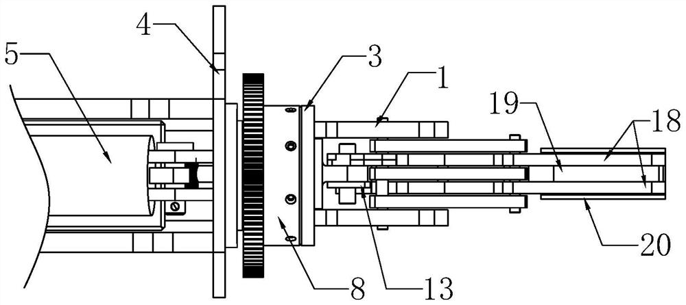
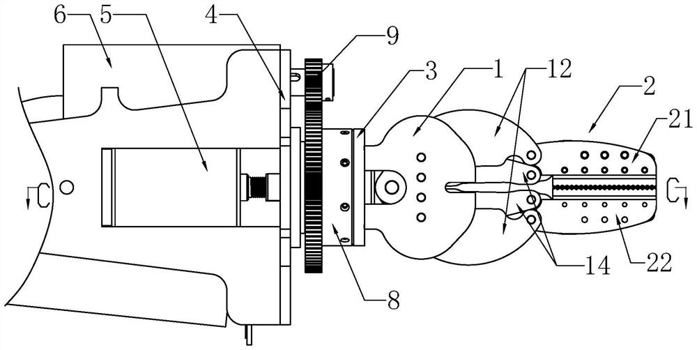
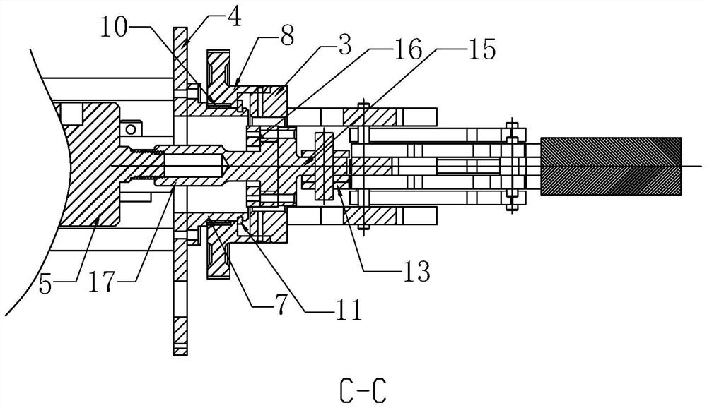
The invention discloses a clamping device with a rotating mechanism. The invention relates to a clamping jaw assembly for a mechanical arm, which comprises two force arm baffle plates, an execution combination part and a clamping jaw assembly, wherein the two force arm baffle plates are fixedly arranged on a connecting ring seat; the mounting base is located behind the connecting ring base, the advancing and retreating driving device is located behind the mounting base and used for driving the executing combined part to move forwards and backwards so as to enable the clamping jaw assembly to horizontally move to be opened and closed, and a rotating driving device used for driving the connecting ring base to rotate is fixedly installed on the mounting base. The rotating driving device drives the connecting ring base to rotate, and then the clamping jaw assembly is driven to rotate through the two force arm baffles. The clamping mechanism has the advantages that the structure is simple and compact, the jaw always keeps translational motion in the opening and closing process through ingenious structural design, meanwhile, the clamping mechanism can rotate forwards and backwards and rotate circumferentially, the function similar to that of a monkey wrench can be achieved, the working efficiency and reliability of the underwater robot are greatly improved, the application range is wide, meanwhile, installation and maintenance are convenient, and the application range is wide. And the cost is low.

Description

technical field [0001] The invention relates to a clamping mechanism of a manipulator, in particular to a clamping device with a rotating mechanism, which belongs to the technical field of robots and manipulators. Background technique [0002] The underwater multi-degree-of-freedom manipulator is one of the core equipment for underwater operations. It is mainly mounted on underwater robots and plays a vital role in the development of marine resources, underwater sampling and the development of deep-water oil and gas fields. The multi-degree-of-freedom hydraulic manipulator can be mounted on the operating ROV. According to the working requirements of the subsea oil tree, it can cooperate with special tools to complete the inspection of underwater oil production and the opening and closing of pipeline valves. The clamping mechanism of the manipulator is very important. It determines the versatility and breadth of tasks that the manipulator can perform. The existing clamping me...

Claims


Application Information

Patent Timeline
IPC IPC(8): B25J15/00B63C11/52
CPCB25J15/00B63C11/52
Inventor 赵飞凌宏杰姚震球郭浩李亿
Owner ZHENJIANG COLLEGE
Learn More