
Detection method and detection circuit of storage unit

A technology of storage unit and detection method, which is applied in the field of memory, can solve the problems of storage unit damage, inability to fully reflect product characteristics, peripheral product characteristics or inconsistent distribution, etc., and achieve the effect of convenient method

Pending Publication Date: 2022-04-22
INST OF MICROELECTRONICS CHINESE ACAD OF SCI +1
View PDF0 Cites 0 Cited by
  • Summary
  • Abstract
  • Description
  • Claims
  • Application Information

AI Technical Summary

Problems solved by technology

However, measurements made at the kerf cannot fully characterize the product
Moreover, with the miniaturization of the semiconductor process, various unknown reasons will lead to inconsistencies between the characteristics measured on the cutting line and the characteristics or distribution of surrounding products
Due to the high demand for the measurement of the actual characteristics of the product, the existing test method will increase the test time required for the adjustment of the product characteristics, thereby increasing the cost
[0003] It is difficult to measure the characteristics of memory cells in products. In order to directly measure the performance of DRAM memory cells inside the product, peripheral circuits need to be modified or added, but such modifications or additions are very difficult to achieve.
[0004] The existing technology can measure the characteristics of the storage unit inside the product, but this test method has a high probability of causing damage to the measured storage unit and affecting the yield of the product, so the measured storage unit needs to be repaired , making it a redundant memory cell (Redundant Memory Cell), resulting in an increase in cost

Method used

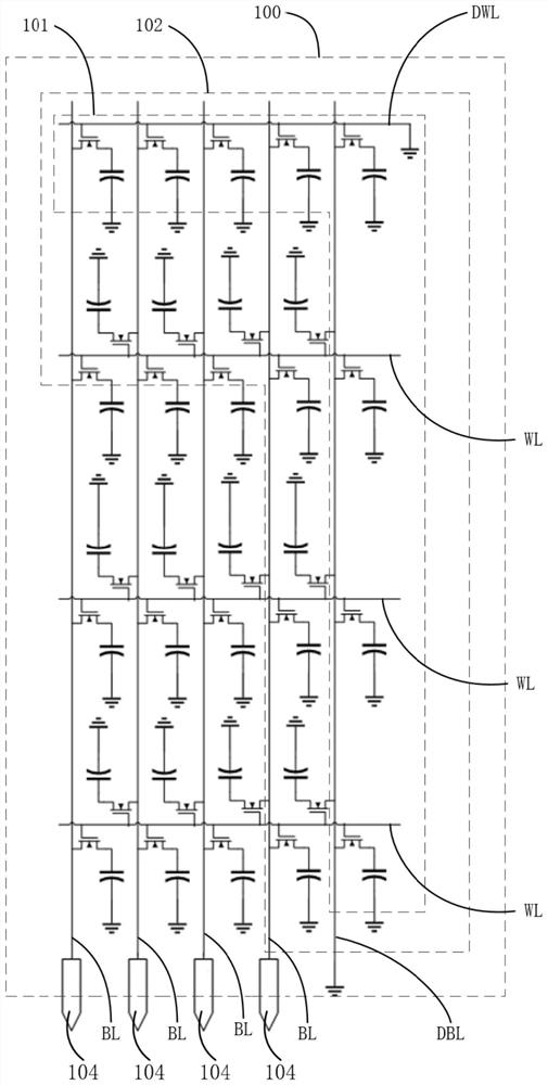
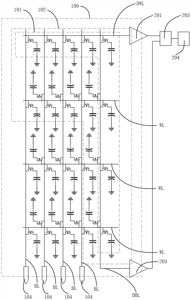
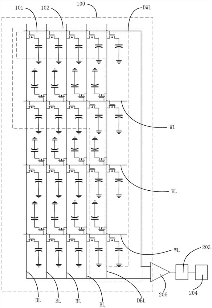

Image

  • Detection method and detection circuit of storage unit
  • Detection method and detection circuit of storage unit
  • Detection method and detection circuit of storage unit

Examples


Embodiment Construction

[0017] Hereinafter, embodiments of the present disclosure will be described with reference to the drawings. It should be understood, however, that these descriptions are exemplary only, and are not intended to limit the scope of the present disclosure. Also, in the following description, descriptions of well-known structures and techniques are omitted to avoid unnecessarily obscuring the concept of the present disclosure.

[0018] Various structural schematic diagrams according to embodiments of the present disclosure are shown in the accompanying drawings. The figures are not drawn to scale, with certain details exaggerated and possibly omitted for clarity of presentation. The shapes of the various regions and layers shown in the figure, as well as their relative sizes and positional relationships are only exemplary, and may deviate due to manufacturing tolerances or technical limitations in practice, and those skilled in the art will Regions / layers with different shapes, s...


PUM


Abstract

The invention relates to a detection method and a detection circuit of a memory cell. The detection method of the storage unit comprises the following steps: before packaging a storage block, connecting one end of a word line and one end of a bit line of an edge unit of the storage block with the input end of a built-in self-test logic circuit through a first amplifier and a second amplifier respectively; applying a measurement voltage or a measurement current to a word line and a bit line connected with the built-in self-test logic circuit; and the measurement result of the edge unit is output through the output end of the built-in self-test logic circuit. One end of a word line and one end of a bit line located in a storage block edge unit are connected with the input end of a built-in self-test logic circuit through a first amplifier and a second amplifier respectively, then measurement voltage or measurement current is applied, and a measurement result is output through the output end of the built-in self-test logic circuit. Performance detection can be performed on the storage block without affecting the storage unit, the method is convenient, and the product yield and the product cost are not affected.

Description

technical field [0001] The present application relates to the technical field of memory, and in particular to a detection method and a detection circuit of a storage unit. Background technique [0002] Due to the reduction in the size of the memory cell of DRAM and the lower operating voltage, the distribution of the memory cells has a great impact on the product performance, and the results of the surrounding measurements cannot reflect the characteristics of the product. It is necessary to adjust the base end bias (Body Bias) of the substrate to minimize the influence caused by the distribution of memory cells. The characteristics of the storage unit are measured through the Scribe Lane, and then the characteristics of the DRAM memory block product are adjusted according to the measured results. However, measurements made at the kerf cannot fully characterize the product. Moreover, with the miniaturization of the semiconductor process, various unknown reasons may lead to...

Claims


Application Information

Patent Timeline
IPC IPC(8): G11C29/12
CPCG11C29/12005G11C29/1201G11C2029/1206
Inventor 李相惇孙永载赵劼杨涛张欣
Owner INST OF MICROELECTRONICS CHINESE ACAD OF SCI
Learn More