Pipeline vibration reduction design method based on viscous damping and particle damping coupling

A particle damping and viscous damping technology, applied in the field of pipeline vibration reduction, can solve the problems of complex frequency components, poor high-frequency vibration damping effect, complex pipelines, etc., achieving good effect, good vibration reduction and noise reduction, and simple and efficient detection. Effect

Pending Publication Date: 2022-04-26
SINOCHEM QUANZHOU PETROCHEM CO LTD +1
View PDF0 Cites 0 Cited by
  • Summary
  • Abstract
  • Description
  • Claims
  • Application Information

AI Technical Summary

Problems solved by technology

[0003] The vibration of the pipeline is a relatively complex systematic problem. The pipeline is equipped with special structures such as valves, tees, and elbows. The vibration characteristics and causes of vibration are different at different positions on the pipeline, and its frequency components are relatively complicated. All pipeline dampers have limitations in their damping frequency bands
For example, the viscous damping damper is a velocity-type damper, which has a good damping effect on low-frequency vibrations, but has a poor damping effect on high-frequency vibrations. For example, a particle damping damper is an acceleration-type damper. The vibration reduction effect of low frequency vibration below 100Hz is not obvious, but the vibration reduction effect of high frequency above 100Hz is very obvious

Method used


Image

  • Pipeline vibration reduction design method based on viscous damping and particle damping coupling
  • Pipeline vibration reduction design method based on viscous damping and particle damping coupling
  • Pipeline vibration reduction design method based on viscous damping and particle damping coupling

Examples


Embodiment Construction

[0034] The present invention will be further described below in conjunction with the accompanying drawings and specific embodiments.

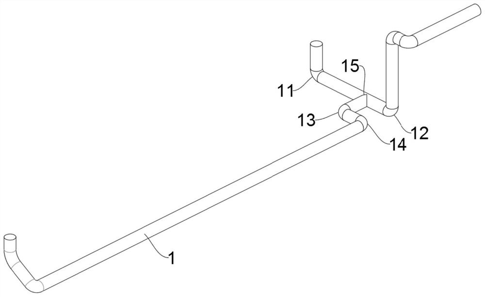
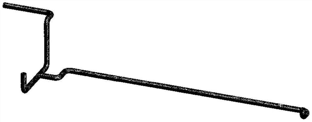
[0035] The invention discloses a pipeline damping design method based on the coupling of viscous damping and particle damping. Vibration damping is performed by arranging a viscous damping damper 2 and a particle damping damper 3 on the outer periphery of a pipeline 1, including the following steps:

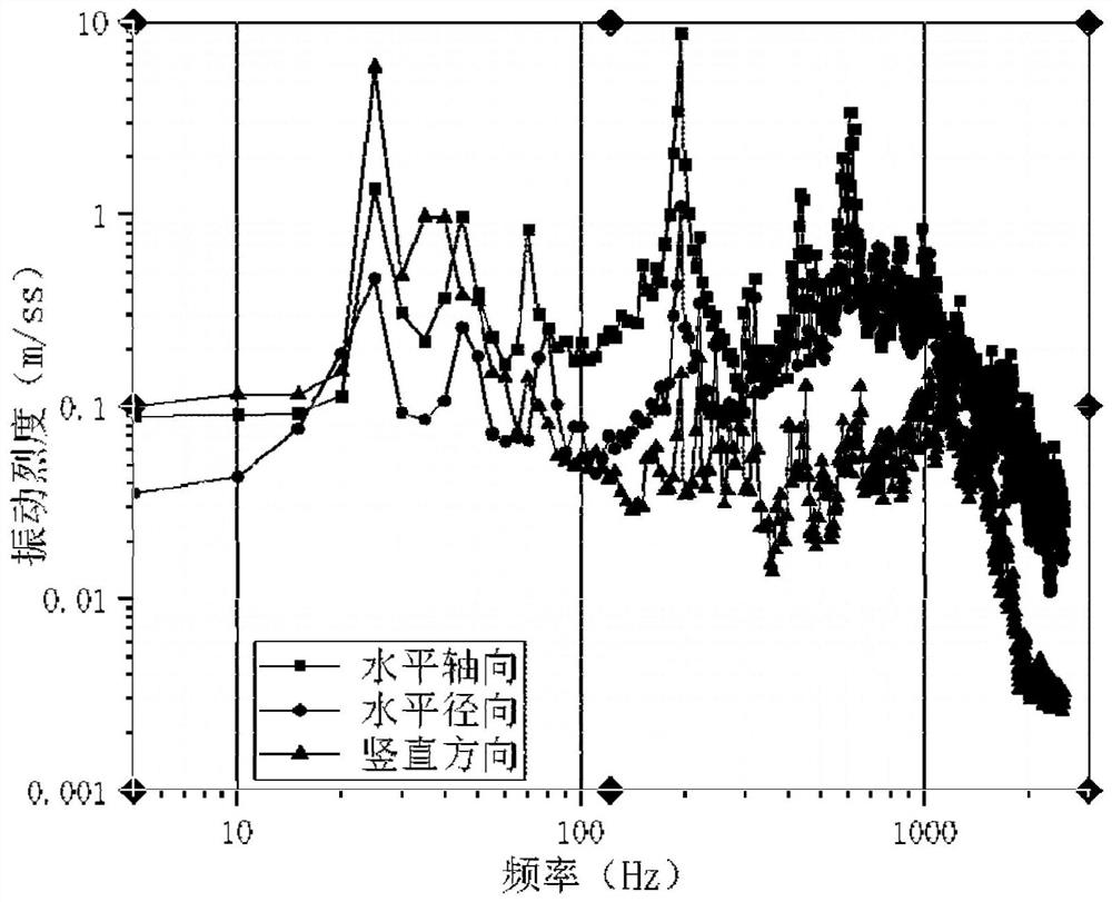
[0036] S1. Conduct a vibration test on the pipeline 1 to be optimized in the running state, extract the vibration frequency characteristics of the pipeline 1 to be optimized, and establish a discrete element-finite element coupling analysis model of the pipeline 1 to be optimized.

[0037] The vibration test is carried out when the pipeline 1 is working. The test system includes an acceleration sensor, a vibration data collector and a data analysis platform. The measurement frequency range of the acceleration sensor is 0.5Hz-12000Hz. The data analy...


PUM


Abstract

The invention discloses a viscous damping and particle damping coupling-based pipeline vibration reduction design method, which comprises the following steps of: carrying out vibration test on a to-be-optimized pipeline, extracting vibration frequency characteristics, establishing a discrete element-finite element coupling analysis model, and calculating the vibration of the to-be-optimized pipeline; vibration damping frequency bands corresponding to the viscous damping vibration damper and the particle damping vibration damper are matched, and various configuration parameters of the vibration damping vibration damper are determined; and performing static analysis mode calculation on the optimized new pipeline to obtain a new pipeline model and a stress distribution diagram of the new pipeline model, and comparing a stress maximum value in the stress distribution diagram with a fatigue limit value of the pipeline to enable the stress maximum value of the new pipeline model to be smaller than the fatigue limit value of the pipeline. According to the method, the vibration reduction characteristics of the viscous damping vibration absorber and the particle damping vibration absorber are utilized, the viscous damping vibration absorber and the particle damping vibration absorber are matched with the discrete element-finite element coupling analysis model of the to-be-optimized pipeline, vibration reduction and noise reduction can be conducted on all vibration frequency bands of the pipeline in a targeted mode, vibration control over the whole frequency band of the pipeline is achieved, and the vibration reduction and noise reduction effect is good.

Description

technical field [0001] The invention relates to the technical field of pipeline vibration reduction, in particular to a pipeline vibration reduction design method based on the coupling of viscous damping and particle damping. Background technique [0002] Pipeline vibration is a common phenomenon in the petrochemical industry. Various reasons such as the opening and closing of valves in the pipeline, the transportation of fluid in the pipeline, and the vibration transmission of machinery will cause pipeline vibration. There are many hazards in pipeline vibration. Severe vibration can even cause fatigue failure of pipeline structure, lead to structural damage of pipeline, cause pipeline rupture, and cause serious safety accidents such as container rupture and explosion. Therefore, the problem of pipeline vibration reduction has attracted much attention. [0003] The vibration of the pipeline is a relatively complex systematic problem. The pipeline is equipped with special str...

Claims


Application Information

Patent Timeline
IPC IPC(8): G06F30/18G06F30/23G06F113/14G06F119/14
CPCG06F30/18G06F30/23G06F2113/14G06F2119/14
Inventor 张华驰刘传云胡壮
Owner SINOCHEM QUANZHOU PETROCHEM CO LTD
Why Eureka
Try Eureka