
Percutaneous aortic valve implantation guide wire

A technology of aortic valve and guide wire, which is applied in the field of medical devices, can solve the problems of uneven distribution of guide wire, aortic distortion, aortic dissection, etc., achieve good bioprofiling, improve the success rate, and reduce the risk of Effect

Pending Publication Date: 2022-04-29
APT MEDICAL HUNAN INC +1
View PDF0 Cites 1 Cited by
  • Summary
  • Abstract
  • Description
  • Claims
  • Application Information

AI Technical Summary

Problems solved by technology

[0004] However, the existing guide wire is linear, and when the guide wire is delivered in the aorta, the angle of the aorta will force the guide wire to bend, and the reaction force of the guide wire bending will cause the aorta to twist, and at the same time, the huge pushing force may cause Aortic dissection, myocardial perforation, resulting in surgical failure and even patient death
Moreover, after the distal end of the guide wire enters the ventricle, the forward force of the guide wire is unevenly distributed at the head end, and it is easy to concentrate on the linear guide wire head, and there is a risk of myocardial injury and perforation

Method used


Image

  • Percutaneous aortic valve implantation guide wire
  • Percutaneous aortic valve implantation guide wire
  • Percutaneous aortic valve implantation guide wire

Examples


Embodiment 1

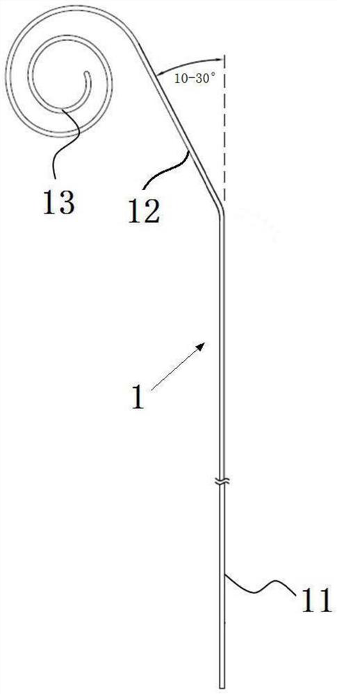
[0080] Such as figure 1 As shown, a percutaneous aortic valve implantation guide wire includes a guide wire body 1,

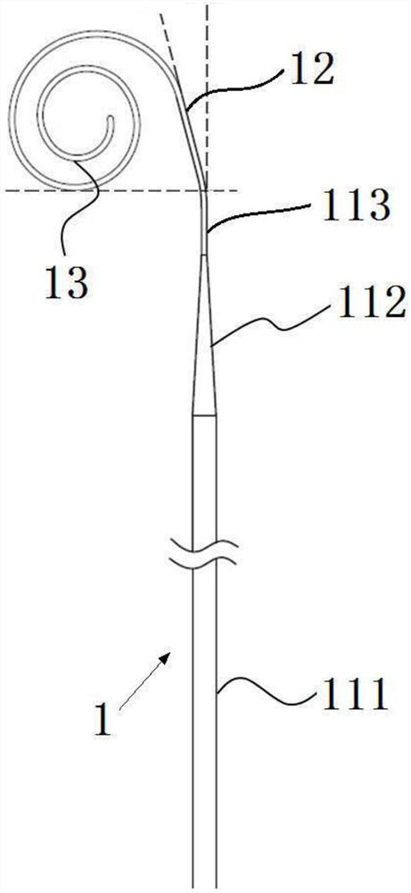
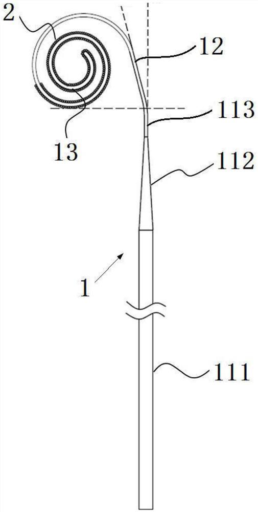
[0081] The guide wire body 1 includes a connected first section 11, a second section 12 and a helical section 13, the first section 11 is located at the proximal end, the helical section 13 is located at the distal end, and the two ends of the second section 12 are respectively connected to the first section 11 and the helical section 13. Helical segment 13;

[0082] There is a first included angle between the first section 11 and the second section 12; the angle of the first included angle is 30°;

[0083] The helical segment 13 is formed by coiling the guide wire into a helical circle, and the helical coils of the helical segment 13 are located in a plane; the number of helical coils of the helical segment 13 is 4 semicircles;

[0084] The plane formed by the first segment 11 and the second segment 12 coincides with the plane where the helical segment 13 is...

Embodiment 2

[0086] Same as Embodiment 1, except that the angle of the first included angle is 20°.

Embodiment 3

[0088] Same as Embodiment 1, the maximum diameter of the helical coil of the helical section 13 is 15 cm.


PUM


Abstract

The percutaneous aortic valve implantation guide wire comprises a guide wire body (1), the guide wire body (1) comprises a first section (11), a second section (12) and a spiral section (13) which are connected, the first section (11) is located at the near end, the spiral section (13) is located at the far end, and the two ends of the second section (12) are connected with the first section (11) and the spiral section (13) respectively; a first included angle is formed between the first section (11) and the second section (12); the spiral section (13) is formed by curling a guide wire into a spiral ring, and the spiral ring of the spiral section (13) is located in the same plane. According to the percutaneous aortic valve implantation guide wire, the guide wire pushing efficiency and speed are improved through the bending between the first section and the second section, the myocardial perforation risk is reduced through the spiral section, the anchoring effect is improved, the structural design is reasonable, operation is easy, mastering is easy, and the percutaneous aortic valve implantation success rate can be increased.

Description

technical field [0001] The present application relates to the technical field of medical devices, in particular to a guide wire for percutaneous aortic valve implantation. Background technique [0002] Percutaneous aortic valve implantation refers to percutaneous puncture or opening of peripheral blood vessels, pushing the catheter to the aortic valve, and performing aortic valve replacement to relieve aortic valve stenosis. It is a treatment for patients with surgical contraindications. First choice for patients with aortic stenosis. [0003] The complex structure of the percutaneously implantable aortic valve requires a large diameter of the delivery sheath, coupled with the patient's aortic sclerosis and distortion, resulting in great tension and resistance when pushing the artificial valve along the delivery sheath to the heart. A guiding wire needs to be placed in the left ventricular lumen as an aortic valve push track to avoid damage to the aortic wall by the deliver...

Claims


Application Information

Patent Timeline
Patent Type & Authority Applications(China)
IPC IPC(8): A61M25/09
CPCA61M25/09A61M2025/09125A61M2025/09175A61M2025/09058
Inventor 宋光远彭晴易沛林张效凯
Owner APT MEDICAL HUNAN INC
Learn More