[0038] Embodiment one:
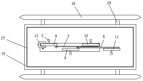
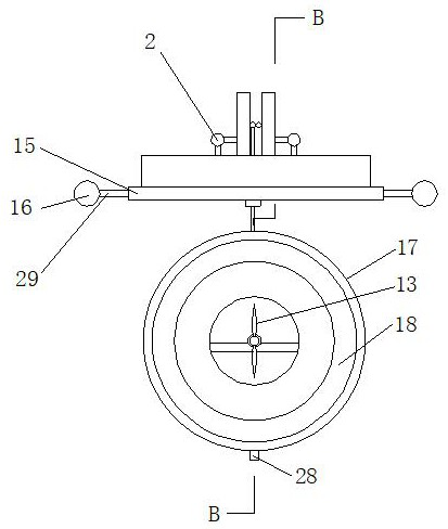
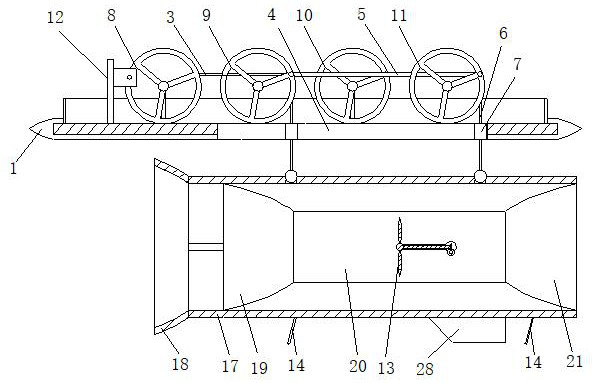
[0039] like figure 1 , figure 2 and image 3 As shown, a floating device for hydrodynamic power generation includes a floating body 1, an adjustment assembly, a rectification assembly and a power generation assembly. The adjustment assembly is arranged on the floating body 1; the floating body 1 includes a bottom plate 15, a connecting plate 29, and two buoys 16 And anti-wave parts 27, bottom plate 15 is arranged along the horizontal direction and is positioned between two buoys 16, each buoy 16 and bottom plate 15 are connected as a whole by connecting plate 29, and bottom plate 15 is provided with a strip hole, and fixed guide rail 4 is fixed In the elongated hole; the anti-wave component 27 is located on the upper surface of the bottom plate and arranged along the outer edge of the bottom plate, forming a closed ring-shaped enclosure structure as a whole; the adjustment component is located in the enclosure circle of the anti-wave component.
[0040] like Figure 4 , Figure 5 and Image 6 As shown, the adjustment assembly includes a mounting base 2, four moving wheels, a horizontal bar 3, a fixed guide rail 4, a moving guide rail 5, a bolt, two connecting rods 6, a first slider and two second sliders 7, four The driving wheels are sequentially recorded as the driving wheel 8, the first driven wheel 9, the second driven wheel 10 and the third driven wheel 11 along the water flow from upstream to downstream. The seat 2 is fixed on the corresponding position of the floating body 1; the outer side of the driving wheel 8 is provided with a stopper 12, and one end of the horizontal rod 3 is connected to the non-center position of the driving wheel 8 in rotation, and the other end of the horizontal rod 3 and the first The slide block is rotationally connected, the first slide block is slidably arranged in the moving guide rail 5, one end of the moving guide rail 5 is rotationally connected with the non-center position of the first driven wheel 9, and the other end of the moving guide rail 5 is connected with the non-circle center of the third driven wheel 11. Position rotation connection, the non-center position of the second driven wheel 10 is provided with a first socket, the end of the connection between the horizontal bar 3 and the first slider is provided with a second socket, and the latch part includes a latch body and is fixed on the latch body. The bearing on the outer side wall, the plug piece can pass through the first insertion hole and be inserted into the second insertion hole.
[0041] like image 3 As shown, the fairing assembly includes a fairing 17, a water diversion pipe 18, a fixed rod, a fixed seat, a water passage and two stabilizing plates. The fairing 17 is a tubular body and is arranged along the direction of water flow. The fairing 17 is located on both sides of the upstream and downstream. A fixed seat is respectively fixed on the inner side wall of the water pipe, and the water pipe 18 is positioned at the upstream of the water passage. One end of the rod is connected, and the other end of the fixed rod is fixed on the fixed seat located in the upstream; the water passage part includes the water inlet pipe 19, the connecting pipe 20 and the water outlet pipe 21 in sequence along the water flow direction, and the water inlet pipe 19 and the water outlet pipe 21 are concentric and different. diameter pipe, the water inlet pipe 19 is fixed on the fixed seat located in the upstream, and the smaller end of the water inlet pipe 19 is connected to the water inlet of the connecting pipe 20. 20, the water outlet of the connecting pipe 20 is connected to the smaller diameter end of the water outlet pipe 21, and the water outlet pipe 21 is fixed on a fixing seat located downstream. The function of the fixing rod is to fix the water diversion pipe on the upstream of the water passage, and mainly plays a connection role. There can be one or more fixed rods, which are welded at the end of the water pipe.
[0042] The fixed guide rail 4 is made up of two channel steels, and the two channel steels are all fixed in the elongated holes along the length direction of the elongated holes on the bottom plate 15, and the notches of the two channel steels are relatively arranged, and each second slide block 7 They are all slidingly clamped in the two grooves of the two channel steels, and each second slider 7 is provided with a first through hole arranged in the vertical direction, and each second slider 7 passes through the first through hole. The hole is movably sleeved on a corresponding connecting rod 6, and the connecting rod is located between two channel steels. The lower ends of the two connecting rods 6 are respectively connected to the upper end of the submerged fairing in rotation, and the upstream one is connected Rod 6, its upper end is rotatably connected with the end of the moving guide rail 5 near the first driven wheel 9; a connecting rod 6 located downstream, its upper end is rotatably connected with the end of the moving guide rail 5 near the third driven wheel 11; the lower end of the fairing 17 Two anchor cables 14 are provided, and the other ends of the anchor cables 14 are fixed on the bottom of the river.
[0043] The stabilizing plate 28 is streamlined, and each stabilizing plate is all fixed on the lower end of the fairing 17 along the length direction of the fairing 17, and is all positioned at the downstream side of the fairing 17, the connecting line of the center of the two stabilizing plates and the side of the fairing The length direction is vertical.
[0044] like Figure 7 As shown, the stopper includes a vertical bar 24 and a U-shaped frame 25, and the U-shaped frame 25 includes two vertical plates and a side plate, and the lower end of the vertical bar 24 is fixed on the floating body bottom plate 15, and the side plate of the U-shaped frame 25 Fixed on the top of the vertical bar 24, a threaded hole is provided on a vertical plate of the U-shaped frame 25, and a bolt 26 is arranged in the threaded hole, and the part of the driving wheel 8 is located between the two vertical plates of the U-shaped frame 25. Bolt 26 is screwed in and extruded driving wheel 8, can make driving wheel 8 stop rotating.
[0045] Mounting seat 2 comprises cross bar and vertical bar, and the lower end of vertical bar is fixed on the bottom plate 15 of floating body, and one end of cross bar is fixed on the upper end of vertical bar; superior.
[0046] The fixed seat is an annular body, and the outer wall of the fixed seat is fixed on the inner measuring wall of the fairing 17, and the water inlet pipe 19 and the water outlet pipe 21 are respectively fixed on the inner measuring wall of the corresponding fixed seat.