Copper foil removing equipment for UWB positioning base station substrate production

A technology for positioning base stations and substrates, applied in the field of electronics, can solve problems such as increased production costs, and achieve the effect of ensuring the effect of etching

Pending Publication Date: 2022-04-29
HANGZHOU CCRFID MICROELECTRONICS
View PDF0 Cites 2 Cited by
  • Summary
  • Abstract
  • Description
  • Claims
  • Application Information

AI Technical Summary

Problems solved by technology

[0005] In order to overcome the situation that the copper foil on the substrate contains impurity particles during lamination, after the copper foil is etched and removed, the impurity particles fall into the blind holes of the substrate, which requires additional processing steps for processing, resulting in increased production costs. , the present invention provides a copper foil removal equipment for UWB positioning base station substrate production

Method used


Image

  • Copper foil removing equipment for UWB positioning base station substrate production
  • Copper foil removing equipment for UWB positioning base station substrate production
  • Copper foil removing equipment for UWB positioning base station substrate production

Examples


Embodiment 1

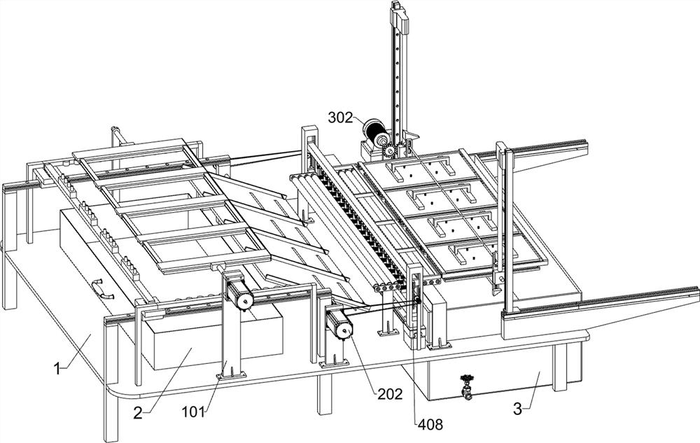
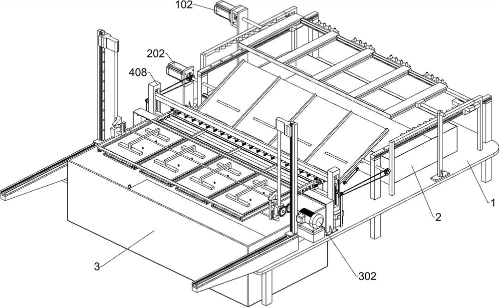
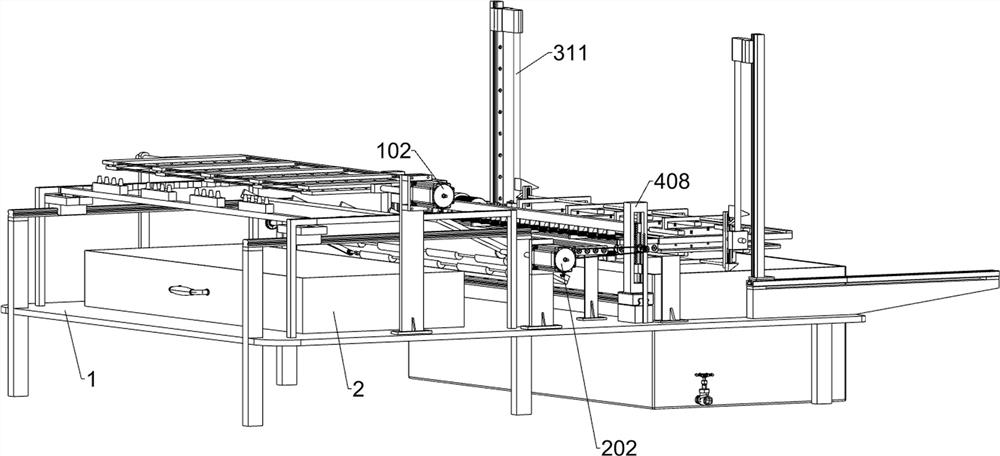
[0037] A copper foil removal equipment for UWB positioning base station substrate production, such as Figure 1-15 As shown, it includes a bottom frame 1, a collection box 2, an etching box 3, a smear removal component, a conveying component and an etching component; the upper left part of the bottom frame 1 is connected to the collection box 2; the right side of the bottom frame 1 is connected to the etching box 3. The upper left part of the bottom frame 1 is connected with a scum removal component, which is located above the collection box 2; the upper left part of the bottom frame 1 is connected with a conveying component; the upper right part of the bottom frame 1 is connected with an etching component .

[0038] The scum removal assembly includes a first fixed plate 101, a first auxiliary motor 102, a first transmission rod 103, a connecting plate 104, a second transmission rod 105, a second fixed plate 106, a first support plate 107, and a bump plate 108 , the second su...

Embodiment 2

[0049] On the basis of Example 1, such as figure 1 and Figure 16-17 As shown, it also includes a water film spraying assembly, the upper middle part of the chassis 1 is connected with a water film spraying assembly, and the water film spraying assembly includes a third transmission wheel 401, a fourth transmission wheel 402, and a sixth transmission rod 403 , the fifth support plate 404, the third spur gear 405, the fourth electric guide rail 406, the fourth electric slider 407, the limit slide rail 408, the fourth mounting plate 409, the nozzle 410, the brush plate 411 and the rack 412; A third transmission wheel 401 is fixedly connected to the opposite side of each third transmission rod 203; a fourth electric guide rail 406 is fixedly connected to the middle part of the upper side of the chassis 1 through a connecting block; two second electric guide rails 406 are slidably connected to each other. Four electric sliders 407; each of the two fourth electric sliders 407 is f...


PUM


Abstract

The invention relates to the technical field of electronics, in particular to copper foil removing equipment for UWB positioning base station substrate production. The technical problem is that a copper foil on a substrate has impurity particles during pressing, after the copper foil is etched and removed, the impurity particles fall into blind holes of the substrate, and additional processing steps need to be added for processing, so that the production cost is increased. According to the technical scheme, the copper foil removing equipment for UWB positioning base station substrate production comprises a bottom frame, a collecting box and the like; a collecting box is connected to the left portion of the bottom frame. When the device is used, residual glue residues in the blind holes of the substrate are cleaned through the air jet, the damage to the substrate is avoided, meanwhile, the adverse effect of the glue residues on etching is avoided, only the lower surface of the substrate is etched through overturning each time, the upper surface is sealed and protected, and the production efficiency is improved. Impurity particles are prevented from falling into the blind holes of the substrate after the copper foil is etched and removed when the copper foil is pressed, and additional processing steps are avoided.

Description

technical field [0001] The invention relates to the field of electronic technology, in particular to a copper foil removal device used for UWB positioning base station substrate production. Background technique [0002] Substrate is the basic material for manufacturing PCB. In general, the substrate is copper-clad laminate. Single-sided and double-sided printed boards are manufactured on the substrate material-copper-clad laminate. Hole processing, chemical Copper plating, copper electroplating, etching and other processing to obtain the required circuit pattern. [0003] In the prior art, during the production of odd-numbered-layer substrates for UWB positioning base stations, the copper foil on both sides of the cured sheet needs to be removed by etching. Since blind holes are formed on the cured sheet through laser drilling, the drop generated during drilling remains on the In blind holes, direct etching will have a negative impact on the removal of copper foil. Spraying...

Claims


Application Information

Patent Timeline
Patent Type & Authority Applications(China)
IPC IPC(8): H05K3/00H05K3/06
CPCH05K3/0055H05K3/0085H05K3/06
Inventor 傅康
Owner HANGZHOU CCRFID MICROELECTRONICS
Why Eureka
Try Eureka