Method for assembling sleeve tank and inner and outer tank supporting device of cryogenic tank car

A supporting device and assembly method technology, applied in the direction of auxiliary devices, workpiece clamping devices, auxiliary welding equipment, etc., can solve problems such as low work efficiency, supporting leg support structure is not suitable for railway transportation, and cracks are easy to occur at the welding connection position , to achieve the effect of improving work efficiency, improving construction efficiency and quality, and improving clarity

Active Publication Date: 2022-05-06
XI AN RAILWAY TRANSPORTATION EQUIP
View PDF5 Cites 0 Cited by
  • Summary
  • Abstract
  • Description
  • Claims
  • Application Information

AI Technical Summary

Problems solved by technology

[0006] The invention provides a method for assembling the inner and outer tank supporting devices of the cryogenic tank car, and aims to solve the problem of low working efficiency and easy occurrence of welded connection positions in the existing inner and outer tank supporting devices of the cryogenic tank car using a cross-bar support structure Cracks, and technical problems with the use of supporting leg structures unsuitable for rail transport

Method used


Image

  • Method for assembling sleeve tank and inner and outer tank supporting device of cryogenic tank car
  • Method for assembling sleeve tank and inner and outer tank supporting device of cryogenic tank car
  • Method for assembling sleeve tank and inner and outer tank supporting device of cryogenic tank car

Examples


Embodiment Construction

[0134] In order to make the solution of the present invention clearer, the present invention will be further described below in conjunction with the accompanying drawings and specific embodiments:

[0135] The invention provides a method for assembling a cryogenic tank car sleeve and an inner and outer tank supporting device, and the specific steps are as follows:

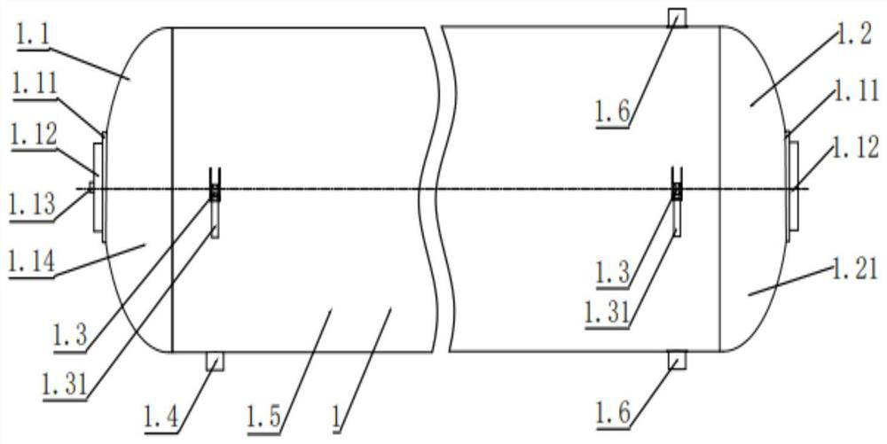
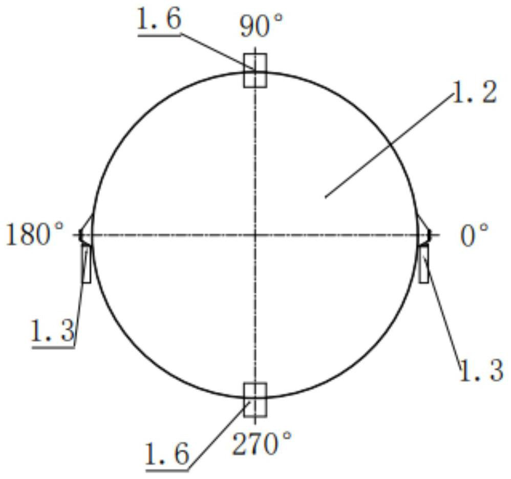
[0136] Step 1, such as figure 1 and figure 2 As shown, the inner tank assembly 1 is assembled and welded.

[0137]Step 1.1, in order to ensure that the 4 inner tank body upper ball joint unit components 1.3 in the inner tank body component 1 are on the same level after being assembled and welded, such as figure 1 As shown, first place a qualified workbench horizontally on the ground of the factory building, and use a spirit level to level the workbench.

[0138] Step 1.2, place the inner tank body assembly 1.5 welded by several barrel sections on the workbench, draw 0°, 90°, 180°, 0°, 90°, 180°, 270° busbar. ...


PUM


Abstract

The invention particularly relates to a cryogenic tank car sleeve tank and an inner and outer tank supporting device assembling method. The method comprises the following steps that 1, an inner tank body assembly is assembled and welded; 2, the inner tank body assembly and the outer tank body assembly are sleeved; 3, longitudinal auxiliary supports, process auxiliary positioning supports and four supporting legs are installed after the inner tank body assembly and the outer tank body assembly are sleeved and combined; 3.1, longitudinal auxiliary supports are welded to the top of the right end of the outer tank assembly and the bottom of the right end of the outer tank assembly correspondingly; the process auxiliary positioning support is welded at the bottom of the left end of the outer tank body assembly; 3.2, assembling and welding a lower spherical hinge unit assembly and a saddle structure of the inner tank body; step 4, welding the first outer seal head and the second outer seal head; installing a transverse auxiliary support at the central position of the first outer sealing head; and 5, the upper saddle assembly and the outer tank body assembly are assembled and welded together. The invention provides an assembling process for sleeving an inner tank body and an outer tank body and a supporting device between the inner tank body and the outer tank body.

Description

technical field [0001] The invention relates to a tank body connection method, in particular to a method for assembling a cryogenic tank car jacket and an inner and outer tank supporting device. Background technique [0002] The temperature of the loaded medium is -253°C or lower for cryogenic railway tank cars. The tank structure is that two sets of cross-rod connection structures are used between the inner and outer tanks. A set of longitudinal tie rods is used to connect the structure; or a support leg type support structure is adopted. [0003] For the cross-bar support structure, the installation of this support structure requires a large number of installation holes on the inner tank body, which brings great difficulties to the assembly, welding and testing of the tank inside and outside the tank, reducing the Production efficiency increases the difficulty and workload of inspection, and the position where the inner tank body is welded to the support structure is pron...

Claims


Application Information

Patent Timeline
Patent Type & Authority Applications(China)
IPC IPC(8): B23P11/00B23K31/02B23K37/00B25B27/00B25B11/00B23K101/12
CPCB23P11/00B23K31/02B23K37/00B25B27/00B25B11/00B23K2101/125Y02E60/32
Inventor 王民锋祁杨朱英波郭小锋候军
Owner XI AN RAILWAY TRANSPORTATION EQUIP
Why Eureka
Try Eureka