Polishing line setting and control method for helmet manufacturing

A control method and helmet technology, which is applied in the directions of automatic grinding control device, workpiece feed movement control, and tool manufacturing, can solve the problems of lower product yield, high labor intensity of employees, and large loss of tools and consumables, etc., to achieve Improve yield rate and quality consistency, reduce labor costs, and improve production efficiency

Active Publication Date: 2022-05-06
广东熙瑞智能科技有限公司
View PDF5 Cites 0 Cited by
  • Summary
  • Abstract
  • Description
  • Claims
  • Application Information

AI Technical Summary

Problems solved by technology

Due to the complex surface shape of the helmet, the degree of grinding required for each position of the injection-molded helmet surface is different. If automatic grinding equipment is used for grinding, the main obstacles are: it is difficult to achieve precise grinding control, and it is difficult to guarantee the grinding of each position The appropriateness of the degree may cause the position that does not need to be polished to be polished or the position that only needs less grinding to be over-polished, which will cause excessive wear of the helmet and affect the quality, reducing the yield of the product.
Therefore, at present, manual grinding is mainly used for helmet grinding, using hand-held electric grinding tools, and grinding control and judgment based on the experience of workers. However, the manual grinding environment is harsh, the labor intensity of employees is high, the grinding efficiency is low, the grinding quality varies greatly, and the quality pass rate Poor, unstable quality; large loss of tools and consumables

Method used


Image

  • Polishing line setting and control method for helmet manufacturing
  • Polishing line setting and control method for helmet manufacturing
  • Polishing line setting and control method for helmet manufacturing

Examples


Embodiment Construction

[0052] The preferred embodiments of the present invention will be described below in conjunction with the accompanying drawings. It should be understood that the preferred embodiments described here are only used to illustrate and explain the present invention, and are not intended to limit the present invention.

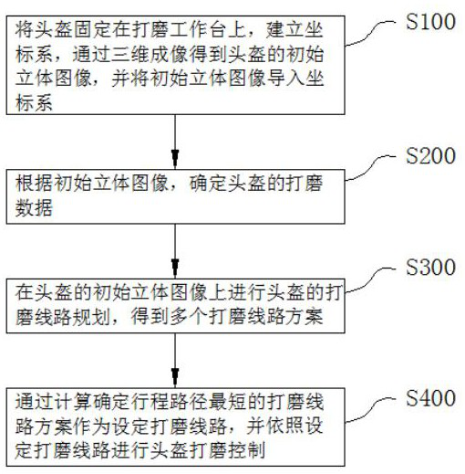
[0053] like figure 1 As shown, the embodiment of the present invention provides a polishing circuit setting and control method for helmet manufacturing, including the following steps:

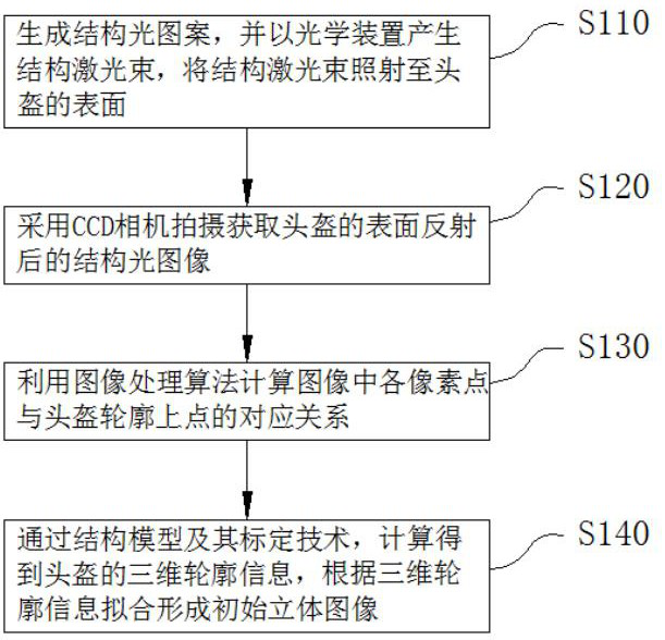
[0054] S100: Fix the helmet on the grinding table, establish a coordinate system, obtain the initial stereoscopic image of the helmet through three-dimensional imaging, and import the initial stereoscopic image into the coordinate system;

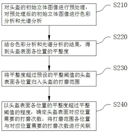
[0055] S200: Determine the polishing data of the helmet according to the initial stereo image;

[0056] S300: Plan the polishing route of the helmet on the initial stereo image of the helmet, and obtain multiple polishing route plans;

[0057] S...


PUM


Abstract

The invention relates to the technical field of helmet polishing control, and particularly provides a polishing line setting and control method for helmet manufacturing, which comprises the following steps: fixing a helmet on a polishing workbench, establishing a coordinate system, obtaining an initial stereo image of the helmet through three-dimensional imaging, and importing the initial stereo image into the coordinate system; determining polishing data of the helmet according to the initial three-dimensional image; carrying out grinding line planning on the helmet on the initial three-dimensional image of the helmet to obtain a plurality of grinding line schemes; and the polishing line scheme with the shortest stroke path is determined through calculation to serve as a set polishing line, and helmet polishing control is conducted according to the set polishing line. According to the invention, accurate helmet polishing line and polishing program control can be realized, the production efficiency is improved, the adverse effects of labor cost and human factors on the product quality are reduced, and the yield and quality consistency of helmets can be improved.

Description

technical field [0001] The invention relates to the technical field of helmet polishing control, in particular to a polishing circuit setting and control method for helmet manufacturing. Background technique [0002] A helmet is a device for protecting the head. The production of a helmet generally requires injection molding, grinding, painting, carving and assembly. Due to the complex surface shape of the helmet, the degree of grinding required for each position of the injection-molded helmet surface is different. If automatic grinding equipment is used for grinding, the main obstacles are: it is difficult to achieve precise grinding control, and it is difficult to guarantee the grinding of each position The appropriateness of the degree may cause the position that does not need to be polished to be polished or the position that only requires less grinding to be over-polished, which will cause excessive wear of the helmet and affect the quality, reducing the yield of the pr...

Claims


Application Information

Patent Timeline
Patent Type & Authority Applications(China)
IPC IPC(8): B24B19/00B24B49/12B24B51/00G06T7/00G06T7/521G06T7/543G06T7/90G06T7/73G06T17/00G06T1/00
CPCB24B19/00B24B49/12B24B51/00G06T7/0006G06T7/521G06T7/543G06T7/90G06T7/73G06T17/00G06T1/0014G06T2207/10012G06T2200/08Y02P90/30
Inventor 陈龙刘业涛熊飞强
Owner 广东熙瑞智能科技有限公司
Why Eureka
Try Eureka