Device and method for reversely pulling and shelling lengthening type torpedo anchor

A technology of pull-back shelling and torpedo anchors, applied in anchor points, transportation and packaging, ship construction, etc., can solve the problems of inability to improve the bearing capacity of torpedo anchors in an all-round way, the overall stability of the unfolded structure, quantity and size constraints and other problems, to avoid the failure of the unfolded structure, save production costs, transportation and installation costs, and reduce its own weight and size.

Active Publication Date: 2022-05-06
NANJING FORESTRY UNIV
View PDF9 Cites 2 Cited by
  • Summary
  • Abstract
  • Description
  • Claims
  • Application Information

AI Technical Summary

Problems solved by technology

However, this solution only expands the bayonet outwards, and the improvement of the bearing capacity is restricted by the number and size of the bayonets.
[0004] Therefore, the prior art often only improves the local bearing capacity of the torpedo anchor unilaterally, and cannot improve the bearing capacity of the torpedo anchor from an overall perspective; due to the decline in the overall stability of some unfolded structures, the lifting bearing capacity is also limited by the deployment. Restricted by conditions such as the rigidity, quantity, and size of the structure, there is still a lot of room for improvement in the pullout performance of the existing torpedo anchors; in addition, because the unfolded structure may be subject to greater resistance from the soil layer, if the unfolded structure is insufficient, it will fail to unfold. Condition

Method used


Image

  • Device and method for reversely pulling and shelling lengthening type torpedo anchor
  • Device and method for reversely pulling and shelling lengthening type torpedo anchor

Examples


Embodiment Construction

[0028] The present invention will be further described below in conjunction with the accompanying drawings and embodiments.

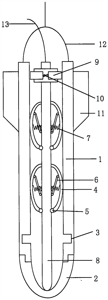
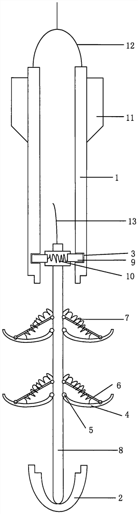
[0029] Such as figure 1 Shown, a kind of device of anti-pull shelling growth type torpedo anchor, comprises anchor body 1, anchor head 2, draw-in groove 3, arc-shaped spreading knife 4, hinge point 5, pull rod 6, high pressure spring 1 7, center bar 8 , chuck 9, high pressure spring II 10, empennage 11, working anchor chain 12, temporary hanging chain 13;

[0030] The anchor head 2 and the anchor body 1 are overlapped by bayonet staggered seams, and can be separated under the action of tension; the top of the anchor head 2 is fixedly connected to the lower end of the middle bar 8, and the anchor head 2 and the middle bar 8 keep moving synchronously;

[0031] Four empennages 11 are symmetrically arranged around the tail of the anchor body 1; a card slot 3 is provided inside the anchor body 1, allowing the chuck head 9 to be fixed under the action of the...


PUM


Abstract

The invention provides a device and a method for reversely pulling a shelling lengthening type torpedo anchor. The device comprises an anchor body, an anchor head, a clamping groove, an arc-shaped unfolding cutter, a hinge point, a pull rod, a high-pressure spring I, a middle lever, a clamping head, a high-pressure spring II, a tail wing, a working anchor chain and a temporary lifting chain. The anchor body and the middle bar are separated through reverse pulling shelling, the length of the torpedo anchor is increased to the maximum extent, the contact area between the torpedo anchor and soil is increased, and the pulling resistance of the torpedo anchor is improved. Multiple sets of arc-shaped unfolding knives can be arranged according to the length of an anchor body, inner arcs of all the arc-shaped unfolding knives face upwards after the arc-shaped unfolding knives are unfolded, the arc-shaped unfolding knives are pulled by a pull rod, the structure stability is high, the arc-shaped unfolding knives and the anchor head form an arc-shaped anti-pulling structure, the situation that unfolding fails due to insufficient unfolding is prevented, and the bearing capacity of the torpedo anchor is fully exerted; the anti-pulling capacity of the torpedo anchor is maximized, the requirements for the self weight and the size of the torpedo anchor are low, lightweight manufacturing of the torpedo anchor can be achieved, the material consumption is reduced, and the manufacturing cost, the transportation cost and the installation cost are saved.

Description

technical field [0001] The invention belongs to the technical field of mooring foundation devices, and in particular relates to a device and method for reverse pulling and shelling growth type torpedo anchors. Background technique [0002] my country's marine resources exploration is moving towards the deep sea, which puts forward high requirements for offshore oil platforms and platform anchoring foundations. At present, the widely used deepwater anchor foundations mainly include suction anchors, normal load-bearing anchors, suction penetration plate anchors, vibration deep buried anchors, and dynamic penetration anchors. Among them, the torpedo anchor is the latest form of deep-sea anchor foundation. It has outstanding features such as low cost, simple and efficient installation, and good anchoring performance. Deep water anchor foundation. The problem encountered at present is that the torpedo anchor can penetrate into the soil by its own gravity, but the pull-out perfo...

Claims


Application Information

Patent Timeline
Patent Type & Authority Applications(China)
IPC IPC(8): B63B21/26
CPCB63B21/26Y02A40/81
Inventor 刘成余思越殷孝天张永兴吕伟华
Owner NANJING FORESTRY UNIV
Why Eureka
Try Eureka