Novel rotary moving mechanism

A moving mechanism and a new type of technology, applied in conveyors, mechanical conveyors, conveyor objects, etc., can solve the problems that simple pulley mechanisms cannot be automatically controlled, do not meet environmental protection claims, and are inconvenient in actual operation, and achieve easy portability. The effect of equipment placement and production cost is low

Inactive Publication Date: 2022-05-06
湖南应用技术学院
View PDF0 Cites 3 Cited by
  • Summary
  • Abstract
  • Description
  • Claims
  • Application Information

AI Technical Summary

Problems solved by technology

[0002] At present, when working in the field, there are only belt transmission mechanisms, forklifts, and pulley mechanisms for repeatedly moving objects (such as concrete, bricks, sand, etc.) at close range. Fixed power supply, but forklift and hydraulic transmission are noisy, high energy consumption, easy to generate noise pollution, and waste a lot of energy, which is not in line with environmental protection, and the simple pulley mechanism cannot be automatically controlled, requiring a dedicated labor force, and the actual operation is extremely inconvenient. Similar equipment that uses less power as a power source to move heavy objects back and forth. For this reason, we propose a new type of rotary movement mechanism to solve the above problems

Method used


Image

  • Novel rotary moving mechanism
  • Novel rotary moving mechanism
  • Novel rotary moving mechanism

Examples


Embodiment 1

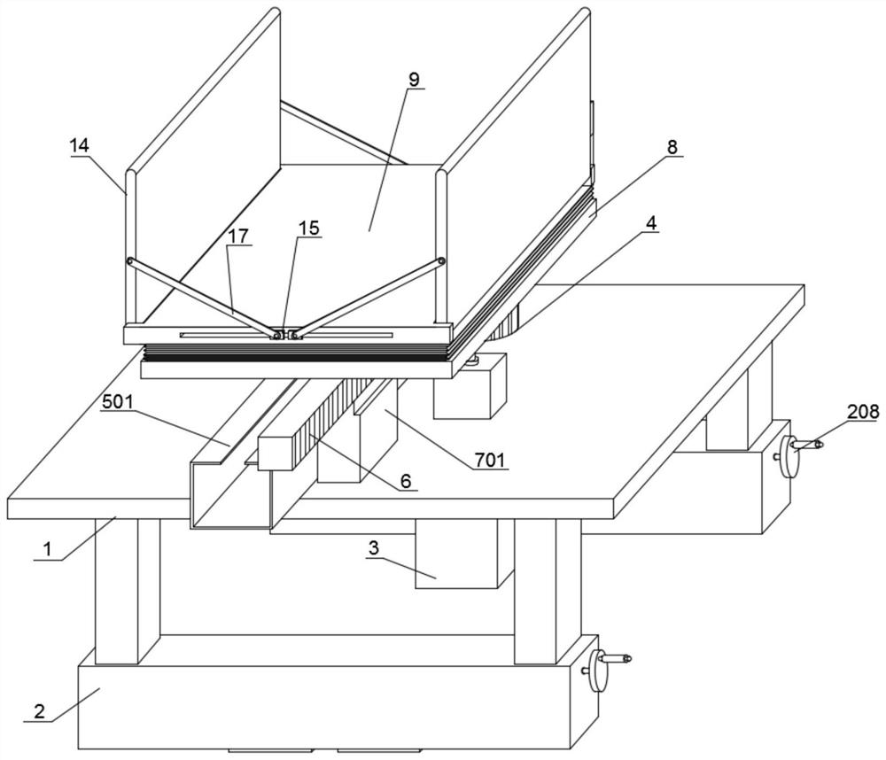
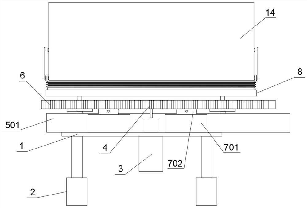
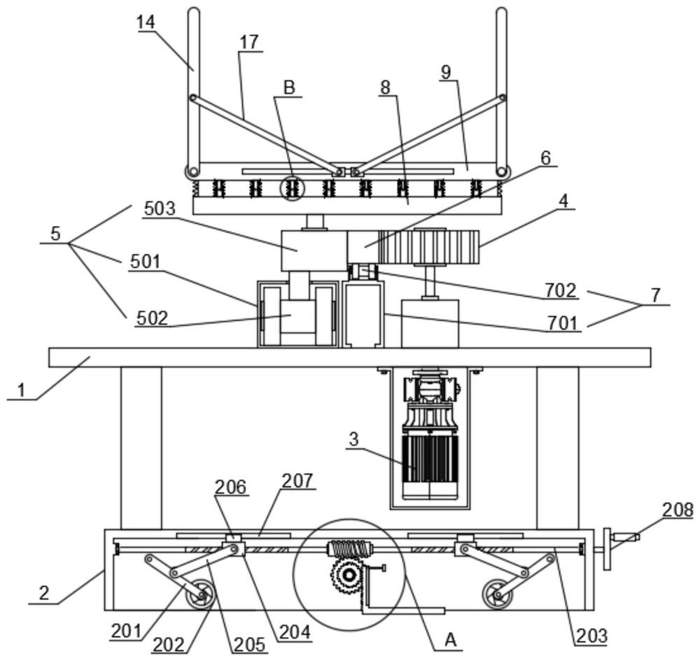
[0028] Embodiment one, by Figure 1-6 Given, a new type of rotary movement mechanism, including chassis 1, mounting shell 2, stepping motor 3, conveying gear 4, pulley assembly 5, conveying rack 6, roller assembly 7, bearing plate 8 and tray 9, the chassis 1 includes the substrate and supporting legs, the substrate is in the shape of a rectangular plate, the four corners of the bottom of the substrate are fixedly installed with supporting legs, the bottom of the supporting legs is fixedly connected with the installation shell 2, the number of the installation shell 2 is two, two installation shells 2 The interior of each is equipped with a moving mechanism, the stepping motor 3 is fixedly installed on the chassis 1, the driving end of the stepping motor 3 extends above the substrate, the conveying gear 4 is fixedly installed on the driving end of the stepping motor 3, and the pulley assembly 5 Set on the top of the chassis 1, the pulley assembly 5 includes a slide rail 501, a ...

Embodiment 2

[0029] Embodiment 2, on the basis of Embodiment 1, the moving mechanism includes a first connecting rod 201, a moving wheel 202, a two-way screw rod 203, a threaded seat 204, a second connecting rod 205 and a rocking wheel 208, and the inside of the installation shell 2 An accommodation groove is provided, and the two-way screw rod 203 is rotatably installed inside the accommodation groove. Two threaded seats 204 are threaded on the two-way screw rod 203, and a second connecting rod 205 is hinged on the threaded seat 204, and the end of the second connecting rod 205 is hinged. In the middle part of the first connecting rod 201, the head end of the first connecting rod 201 is rotationally connected with the inner wall of the receiving tank, the end of the first connecting rod 201 is equipped with a moving wheel 202, and one end of the two-way screw rod 203 extends through the side wall of the receiving tank to the installation The outside of the shell 2 is fixedly connected with...

Embodiment 3

[0030] Embodiment 3, on the basis of Embodiment 1, the shock absorbing mechanism includes a shock absorbing sleeve 10, a piston plate 11, a shock absorbing rod 12 and a shock absorbing spring 13, and a plurality of shock absorbing sleeves 10 are installed on the top of the bearing plate 8, A plurality of damping sleeves 10 are evenly distributed, and the inside of the damping sleeve 10 is slidably connected with a piston plate 11, and the top surface of the piston plate 11 is fixedly equipped with a damping rod 12, and the top wall of the damping sleeve 10 is provided with a shock absorber. The opening through which the rod 12 passes, the top of the shock absorbing rod 12 passes through the opening and is fixedly connected with the bottom surface of the tray 9, the shock absorbing spring 13 is sleeved on the outside of the shock absorbing sleeve 10, and the top of the shock absorbing spring 13 is offset against the bottom surface of the tray 9, The bottom end of the shock absor...


PUM


Abstract

The invention discloses a novel rotary moving mechanism, and relates to the technical field of transportation equipment, the novel rotary moving mechanism comprises a bottom frame, a mounting shell, a stepping motor, a conveying gear, a pulley assembly, a conveying rack, a roller assembly, a bearing plate and a tray, the bottom frame comprises a base plate and supporting legs, and the base plate is in a rectangular plate shape; supporting legs are fixedly installed at the four corners of the bottom of the base plate, two installation shells are fixedly connected to the bottoms of the supporting legs, moving mechanisms are arranged in the two installation shells, and the stepping motor is fixedly installed on the bottom frame. According to the device, the stepping motor drives the conveying gear and the conveying rack to move, the conveying gear and the conveying rack convert rotary motion into linear motion, then a heavy object is moved back and forth through the pulley assembly and the roller assembly, manpower and labor are saved, noise pollution is reduced, energy is saved, the environment is protected, and the device is low in cost, can be repeatedly used and conforms to the claim of environmental protection.

Description

technical field [0001] The invention relates to the technical field of transportation equipment, in particular to a novel rotary movement mechanism. Background technique [0002] At present, when working in the field, there are only belt transmission mechanisms, forklifts, and pulley mechanisms for repeatedly moving objects (such as concrete, bricks, sand, etc.) at close range. Fixed power supply, but forklift and hydraulic transmission are noisy, high energy consumption, easy to generate noise pollution, and waste a lot of energy, which is not in line with environmental protection, and the simple pulley mechanism cannot be automatically controlled, requiring a dedicated labor force, and the actual operation is extremely inconvenient. Similar equipment that uses less power as a power source to move heavy objects back and forth. For this reason, we propose a new type of rotary movement mechanism to solve the above problems. Contents of the invention [0003] The invention ...

Claims


Application Information

Patent Timeline
Patent Type & Authority Applications(China)
IPC IPC(8): B65G35/00B65G47/74
CPCB65G35/00B65G47/74
Inventor 郭奕文庹春菊雷绳飞温朝阳
Owner 湖南应用技术学院
Why Eureka
Try Eureka