Eureka AIR delivers breakthrough ideas for toughest innovation challenges, trusted by R&D personnel around the world.

Injection molding heat exchanger device

A technology of injection molding and injection molding technology, which is applied in the direction of heat exchanger sealing device, indirect heat exchanger, heat exchanger type, etc., can solve the problems of high skill level requirements, limited production capacity improvement, and difficult processing, etc. Achieve the effect of simplifying the processing procedure, improving production efficiency and reducing the difficulty of manufacturing

Pending Publication Date: 2022-05-06
江西省瑞科制冷科技有限公司
View PDF0 Cites 0 Cited by
  • Summary
  • Abstract
  • Description
  • Claims
  • Application Information

AI Technical Summary

Problems solved by technology

[0002] The existing shell-and-tube heat exchanger is basically manufactured by welding the end plates of steel pipes to form a shell, and the heat-exchanging copper tubes in the middle and the baffles adopt the form of sweeping heat exchange to realize indirect heat exchange. This structure has the following problems : First, the steel pipe and the end plate need to be sealed by welding, which is difficult to process, with many and complicated manufacturing processes, and welding defects are prone to affect the quality; second, the production is labor-consuming and time-consuming, and requires high skill levels of personnel, which directly limits the production capacity. increase, resulting in production bottlenecks

Method used


Image

  • Injection molding heat exchanger device
  • Injection molding heat exchanger device
  • Injection molding heat exchanger device

Examples


Embodiment Construction

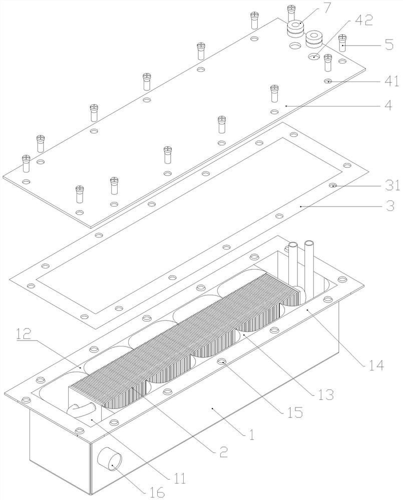
[0026] For describing in detail the technical features of the present invention and the achieved objects and effects, further description is done below in conjunction with the accompanying drawings:

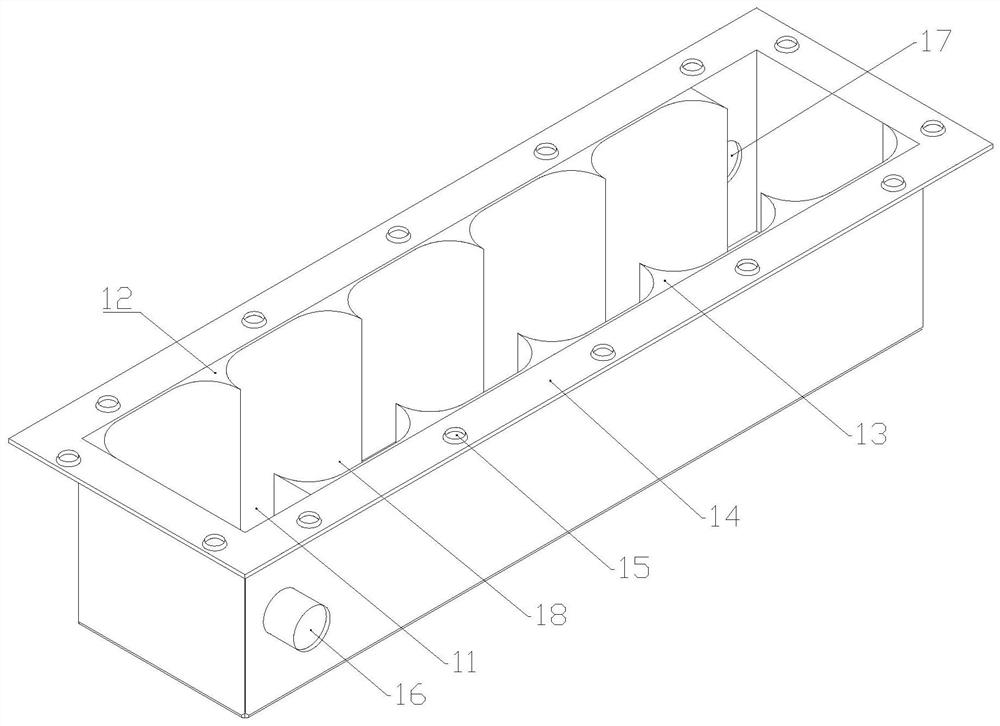
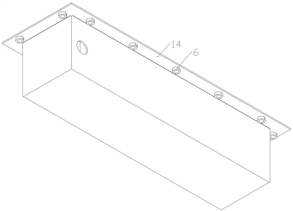
[0027] like Figure 1-6 As shown, an injection molding heat exchanger device includes a plastic shell 1, the plastic shell 1 is integrally formed by an injection molding process, and the plastic shell 1 includes a groove 11 opened inside and the front and rear inner walls of the groove 11 The positions of the first baffle 12 and the second baffle 13 are arranged symmetrically in the center, and the first baffle 12 and the second baffle 13 A cooling liquid channel 18 is formed between 13, the plastic shell 1 is provided with a cooling liquid inlet 16 on the left side of the front wall, and a cooling liquid outlet 17 on the right side of the rear wall; a heat exchange core 2 is installed in the groove 11, and the heat exchange The core 2 includes end plates 21 at the left and righ...


PUM

PropertyMeasurementUnit
depthaaaaaaaaaa

Abstract

The invention relates to the technical field of heat exchangers, and discloses an injection molding heat exchanger device which is characterized in that a plastic shell integrally formed through an injection molding process is adopted, the plastic shell comprises a groove formed inside, a first baffle plate and a second baffle plate, the first baffle plate and the second baffle plate are arranged on the front inner wall and the rear inner wall of the groove, and a cooling liquid channel is formed between the first baffle plate and the second baffle plate; a cooling liquid outlet is formed in the right side of the rear wall of the plastic shell; a heat exchange core is installed in the groove and comprises end plates at the left end and the right end and a plurality of aluminum fins evenly distributed between the two end plates, and the end plates and the aluminum fins are fixed to the heat exchange copper pipe. A plastic cover plate is installed on the plastic shell, two copper pipe via holes are formed in the plastic cover plate, and a heat flow inlet and a heat flow outlet in the heat exchange copper pipe penetrate through the copper pipe via holes and extend to the position above the plastic cover plate. The invention aims to simplify the production and processing procedures of the heat exchanger, improve the production efficiency, reduce the production difficulty and save the labor cost.

Description

technical field [0001] The invention relates to the technical field of heat exchangers, in particular to an injection molding heat exchanger device. Background technique [0002] The existing shell-and-tube heat exchanger is basically made by welding the end plates of steel pipes to make the shell, and the heat exchange copper tubes and baffles are passed through the middle to realize indirect heat exchange in the form of swept heat exchange. This structure has the following problems. : First, the steel pipe and the end plate need to be welded and sealed, which is difficult to process, and the production process is many and complicated, and it is easy to have welding defects and affect the quality; Second, the production is labor-intensive and time-consuming, and the high skill level of personnel is required, which directly limits the production capacity. increase, resulting in production bottlenecks. [0003] Therefore, it is necessary to develop a simplified shell heat ex...

Claims


Application Information

Patent Timeline
Patent Type & Authority Applications(China)
IPC IPC(8): F28D7/00F28F9/00F28F9/24F28F21/06F28F9/26F28F1/32F28F11/00
CPCF28D7/00F28F9/001F28F9/24F28F21/062F28F9/26F28F9/005F28F1/32F28F11/00F28F2255/143
Inventor 周海峰
Owner 江西省瑞科制冷科技有限公司
Why Eureka
Eureka Blog
Learn More