Rotary table structure for automatic test of motor

An automatic test and brake technology, which is applied in the direction of motor generator test, parts of electrical measuring instruments, measuring electricity, etc., can solve problems affecting measurement results, inaccurate shaft coaxiality, poor motor performance, etc., and achieve the adjustment method Simple, guaranteed coaxiality and reliable effect

Active Publication Date: 2022-05-06
CHENGDU ELECTRIC MFG CO
View PDF19 Cites 2 Cited by
  • Summary
  • Abstract
  • Description
  • Claims
  • Application Information

AI Technical Summary

Problems solved by technology

[0003] However, this way of setting multiple couplings makes the axial length of the entire measurement installation structure very long, and the coaxiality of the shafts is slightly inaccurate, which will affect the measurement results
In addition, the way of connecting with the coupling itself cannot guarantee the coaxiality
[0004] The principle of the influence of coaxiality is: when the coaxiality is not good, the force exerted by the number of pole pairs of the motor on the motor shaft will change, the motor is not in a good running state, and the measured performance of the motor is also in a bad state. make measurements inaccurate

Method used


Image

  • Rotary table structure for automatic test of motor
  • Rotary table structure for automatic test of motor
  • Rotary table structure for automatic test of motor

Examples


Embodiment Construction

[0057] The present invention will be further described below in conjunction with the accompanying drawings, but the protection scope of the present invention is not limited to the following description.

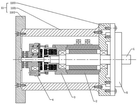
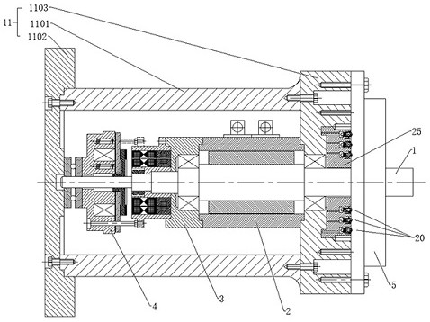
[0058] Such as figure 1 with figure 2 As shown, the turntable structure for automatic motor testing includes a mounting frame 11, a torque sensor 2, a resolver 3, and a spring-applied brake 4;

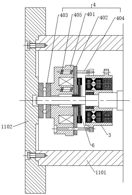
[0059] Wherein, the installation frame 11 includes a central cylinder 1101 and left end caps 1102 and right end caps 1103 at both ends; in the central cylinder 1101, a central shaft 1 is provided along the axial direction, and the central shaft is sequentially threaded with springs from left to right. Brake 4, force plate 6, resolver 3, torque sensor 2;

[0060] Wherein, torque sensor 2, its right end is fixed on the mounting frame 11; Resolver 3, is fixed on the left end surface of torque sensor 2; Spring applied brake 4, its left end is arranged on the mounting frame 11; Pressuriz...


PUM


Abstract

The invention relates to a rotary table structure for automatic testing of a motor, and the structure comprises a mounting frame which is internally provided with a central shaft; the torque sensor is arranged on the central shaft in a penetrating manner, and the right end of the torque sensor is fixed on the mounting frame; the rotary transformer also penetrates through the central shaft and is fixed on the left end surface of the torque sensor; the left end of the spring pressurizing brake is arranged on the mounting frame; a motor is installed on the right end face of the installation frame, and the center shaft is installed in a mounting hole of the motor in a matched mode. The center shaft is provided with a stress disc; the spring pressurization brake generates axial pressure on the stress disc, so that the stress disc is subjected to friction force, and finally the center shaft generates load. An axial position adjusting unit is further arranged on the right side face of the mounting frame. The device has the beneficial effects that the measurement precision is high, the coaxiality can be automatically adjusted, and rigid support can be realized after flexible adjustment.

Description

technical field [0001] The invention relates to the technical field of motor performance measurement, in particular to a turntable structure for automatic testing of motors. Background technique [0002] In the process of measuring torque and other performances of the motor, the shaft of the motor is usually connected to the shaft of the torque sensor by using a coupling, and the shaft of the torque sensor is also connected to the load. [0003] However, this way of setting multiple couplings makes the axial length of the entire measurement installation structure very long, and the coaxiality of the shafts is slightly inaccurate, which will affect the measurement results. In addition, the way of connecting with the coupling itself cannot guarantee the coaxiality. [0004] The principle of the influence of coaxiality is: when the coaxiality is not good, the force exerted by the number of pole pairs of the motor on the motor shaft will change, the motor is not in a good runni...

Claims


Application Information

Patent Timeline
Patent Type & Authority Applications(China)
IPC IPC(8): G01R31/34G01R1/02G01R1/04G01L3/00
CPCG01R31/34G01R1/02G01R1/0408G01L3/00
Inventor 蒲宝星谢海东石利俊张绍贤钱登攀
Owner CHENGDU ELECTRIC MFG CO
Why Eureka
Try Eureka