
Eureka
For R&D, Eureka makes reading and utilizing patents & technical documents easy.
Eureka AIR
Designed for self-driven R&D workflows. Generate viable solutions, solve complex R&D challenges, empower your innovation with AI.

Eureka Materials
Designed for material experts only. Revolutionize your material R&D, from search, analyze, to developing new materials.

TechResearch
Generate reliable direction feasibility study reports for your R&D in just a few steps.

TechSeek
Discover and master advanced knowledge NOW. Basics, ideas, possibilities, all at once.

TechMind
As an expert in R&D Theories, TechMind can generates customized viable solutions instantly.

TechRisk
Analyze your overall solution with one click, know your potential R&D risks in advance.

TechMonitor
Get weekly tech updates, stay abreast of the latest tech innovations and key insights.
Filter circuit
A filter circuit and filter capacitor technology, which is applied to circuit devices, printed circuit components, electrical components, etc., can solve problems such as difficulty in suppressing common-mode noise, and achieve a good effect of conduction noise
- Summary
- Abstract
- Description
- Claims
- Application Information
AI Technical Summary
Problems solved by technology
Method used
Image

Examples
Embodiment 1
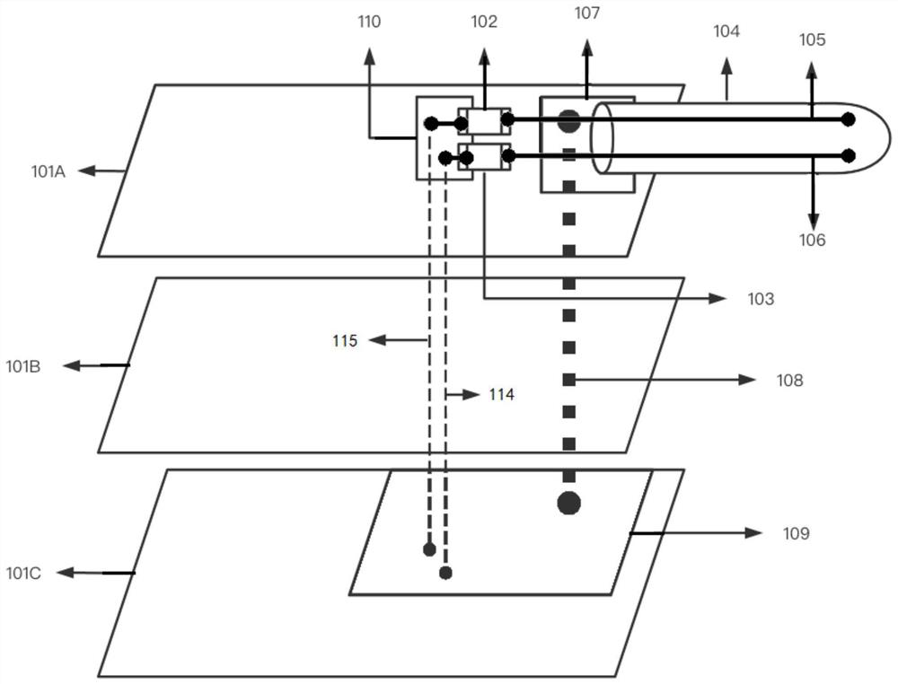
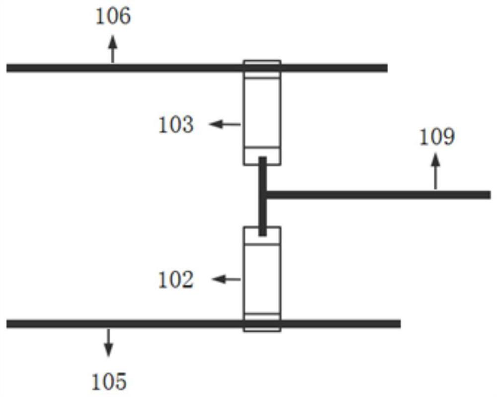
[0034] Such as figure 1 The shown filter circuit includes a first PCB layer 101A and a second PCB layer 101C; the first PCB layer includes a power line 104, a power interface 107, a second filter capacitor 102, and a first filter capacitor 103; the power line 104 includes Power network 106, GND network 105; The second PCB layer 101C includes a conductor plane 109; The power interface 107 is connected to the GND network 105, and the power interface 107 is also connected to the conductor plane 109 through the first metal via 108; GND network 105 and the second filter One end of the capacitor 102 is connected, and the other end of the second filter capacitor 102 is connected to the conductor plane 109 through the third metal via 115; the power supply network 106 is connected to one end of the first filter capacitor 103, and the other end of the first filter capacitor 103 is connected through the second metal via. The hole 114 is connected to the conductor plane 109 . An intermed...
Embodiment 2
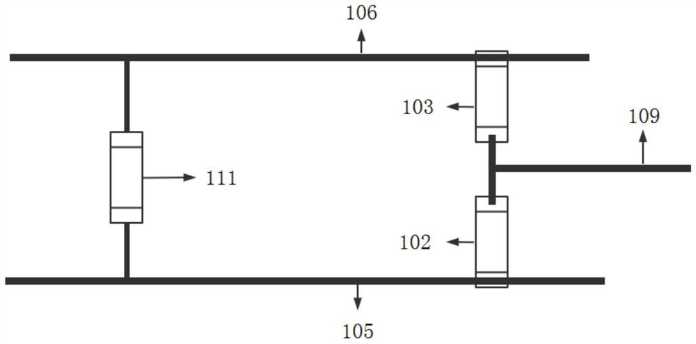
[0038] The difference between Embodiment 2 and Embodiment 1 is that it also includes a third filter capacitor 111, one end of the third filter capacitor 111 is connected to the power supply network 106, and the other end is connected to the GND network 105, such as image 3 shown.
[0039] The third filter capacitor 111 is added to further optimize the filtering effect of differential mode noise, because the third filter capacitor 111 provides another noise current path for differential mode noise, and the specific path is GND network 105 -> third filter capacitor 111 -> power supply Network 106 or power supply network 106->third filter capacitor 111->105GND network. The third filter capacitor 111 can be one filter capacitor or multiple filter capacitors, and the capacitance of the capacitor can be selected according to the required filter frequency, such as 1nF or 100pF.
[0040] Figure 5 It is the conduction noise test result of the filter circuit without using the circui...
Embodiment 3
[0043] The difference between Embodiment 3 and Embodiment 2 is that it also includes a first filtering module 112 and a second filtering module 113. The first filtering module 112 is arranged on the power supply network 106, and the second filtering module 113 is arranged on the GND network 105. The first filter module 112 and the second filter module 113 are inductors or magnetic beads or common mode choke coils, such as Figure 4 shown.
[0044] A first filtering module 112 and a second filtering module 113 are added to further optimize the filtering effect of common mode noise. The first filter module 112 and the second filter module 113 can be inductors, magnetic beads, and common mode choke coils. The number of the first filter module 112 and the second filter module 113 can be multiple, depending on the current size of the actual circuit and the desired filter frequency selection.
PUM
 Abstract
Description
Claims
Application Information
 - R&D Engineer
- R&D Manager
- IP Professional
- Industry Leading Data Capabilities
- Powerful AI technology
- Patent DNA Extraction
Browse by: Latest US Patents, China's latest patents, Technical Efficacy Thesaurus, Application Domain, Technology Topic, Popular Technical Reports.
© 2024 PatSnap. All rights reserved.Legal|Privacy policy|Modern Slavery Act Transparency Statement|Sitemap|About US| Contact US: help@patsnap.com