Horizontal milling machine spindle

A milling machine spindle, horizontal technology, used in metal processing equipment, metal processing mechanical parts, manufacturing tools and other directions, can solve the problems of bearing damage, complicated installation, time-consuming knockout process, etc., to meet rigid requirements, save maintenance costs, The effect of reducing the difficulty of assembly

Pending Publication Date: 2022-05-10
深圳市爱贝科精密工业股份有限公司
View PDF0 Cites 2 Cited by
  • Summary
  • Abstract
  • Description
  • Claims
  • Application Information

AI Technical Summary

Problems solved by technology

With the development of the domestic machine tool industry and the functional subdivision of mechanical processing technology, the spindle of horizontal CNC milling machine is more and more widely used in the market, but the structure of the existing spindle is too complicated to meet the needs of mass production. Most of its high-precision coordination can only be operated manually, so the efficiency of its assembly process is also very important in the entire spindle production process. In the existing milling machine spindle assembly technology, due to the large mounting surface of the front end of the shaft core, the cutter head is relatively large. The front-end bearing gland can only be pushed in and installed at the rear end of the shaft core before installing the bearing, and the step height of the end surface of the bearing gland determines the press-in amount of the outer ring of the bearing, which needs to be measured by measuring the distance between the end surface of the bearing chamber and the end surface of the spacer ring. As a real matching part that needs to be measured and then processed, if its installation sequence is before the bearing, it needs to be matched before the bearing is installed. The existing method is to install the bearing into the bearing first. In the chamber, after measuring the height difference between the end face of the bearing chamber and the end face of the spacer, the bearing gland is installed, and then the bearing is taken out of the bearing chamber, and then the bearing gland, spacer, and bearing are inserted into the shaft core in sequence , and then install the order of the bearing chamber
This process is not only complicated to install, especially when the bearing is taken out of the bearing chamber, because the outer ring of the roller bearing and the bearing chamber are in a transition fit, the process of knocking out is time-consuming and easy to cause damage to the bearing

Method used


Image

  • Horizontal milling machine spindle
  • Horizontal milling machine spindle
  • Horizontal milling machine spindle

Examples


Embodiment Construction

[0032] The present invention will be described in more detail below in conjunction with the accompanying drawings and embodiments.

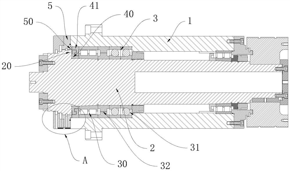
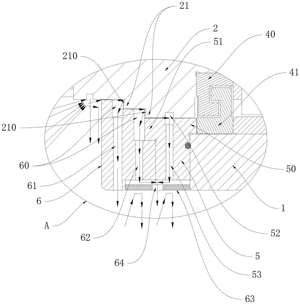
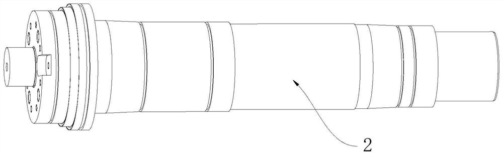
[0033] The invention discloses a horizontal milling machine spindle, which combines Figure 1 to Figure 8 As shown, it includes a bearing chamber 1 and a shaft core 2 passing through the bearing chamber 1. The front bearing assembly 3 and an inner spacer ring 40 are sleeved on the shaft core 2. The front end of the shaft core 2 A front step portion 20 is formed, and the inner spacer ring 40 is sandwiched between the front step portion 20 and the front bearing assembly 3 , the outer side of the inner spacer ring 40 is sleeved with an outer spacer ring 41 and both There is a gap between them, the front end of the bearing chamber 1 is fixed with a front bearing cover 5, a gap is provided between the front bearing cover 5 and the shaft core 2, and the rear end of the front bearing cover 5 A rear resisting convex ring 50 is formed, and the rear resis...


PUM


Abstract

The invention discloses a horizontal milling machine spindle which comprises a bearing chamber and a spindle core arranged in the bearing chamber in a penetrating mode, the spindle core is sleeved with a front bearing assembly and an inner spacer ring, a front step part is formed at the front end of the spindle core, and the inner spacer ring is arranged between the front step part and the front bearing assembly in a clamped mode. The outer side of the inner spacer ring is sleeved with an outer spacer ring, a gap is formed between the inner spacer ring and the outer spacer ring, a front bearing gland is fixed to the front end of the bearing chamber, a gap is formed between the front bearing gland and the shaft core, and a rear resisting convex ring is formed at the rear end of the front bearing gland. The rear resisting convex ring is clamped between the inner wall of the opening in the front end of the bearing chamber and the front step part, and the rear resisting convex ring is in abutting fit with the outer spacer ring. Compared with the prior art, the front bearing gland can be pushed from the front end of the shaft core, so that the assembly difficulty is reduced, the maintenance cost is saved, and meanwhile, the rigidity requirement can be met.

Description

technical field [0001] The invention relates to a main shaft, in particular to a horizontal milling machine main shaft. Background technique [0002] Horizontal CNC milling machine is a machine tool with high efficiency and stable quality. Due to many rough machining processes, the milling machine spindle usually has the characteristics of high rigidity and heavy-duty cutting load. With the development of the domestic machine tool industry and the functional subdivision of mechanical processing technology, the spindle of horizontal CNC milling machine is more and more widely used in the market, but the structure of the existing spindle is too complicated to meet the needs of mass production. Most of its high-precision coordination can only be operated manually, so the efficiency of its assembly process is also very important in the entire spindle production process. In the existing milling machine spindle assembly technology, due to the large mounting surface of the front en...

Claims


Application Information

Patent Timeline
Patent Type & Authority Applications(China)
IPC IPC(8): B23B19/02
CPCB23Q1/70
Inventor 欧阳潜
Owner 深圳市爱贝科精密工业股份有限公司
Why Eureka
Try Eureka