Pneumatic crane

A crane and rotating groove technology, which is applied in the direction of grinding machine parts, load hanging components, metal processing equipment, etc., can solve the problem of wire rope rust being difficult to deal with, and achieve the purpose of avoiding random splashing, reducing burden and improving work efficiency. Effect

Pending Publication Date: 2022-05-10
SHAOXING NANTE HOISTING EQUIP CO LTD
View PDF0 Cites 0 Cited by
  • Summary
  • Abstract
  • Description
  • Claims
  • Application Information

AI Technical Summary

Problems solved by technology

[0005] The purpose of the present invention is to at least solve one of the technical problems in the prior art, and provide a pneumatic crane that can solve the problem that the rust on the wire rope is not easy to handle

Method used


Image

  • Pneumatic crane
  • Pneumatic crane
  • Pneumatic crane

Examples


Embodiment 1

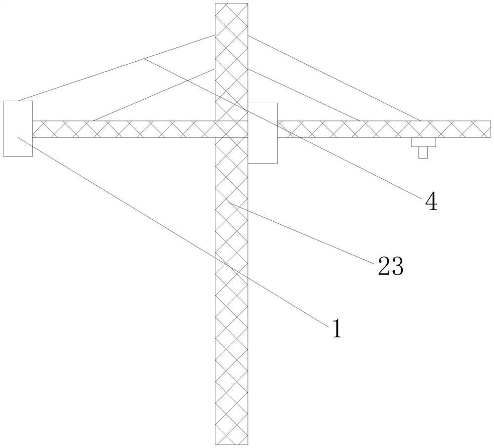
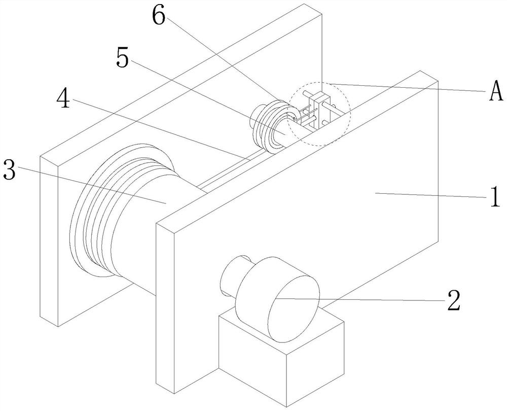
[0033] see Figure 1-2 , the present invention provides a technical solution: a pneumatic crane, including a pneumatic crane body 23, a fixed frame 1, a motor 2, a wire roller 3, a steel wire rope 4, a fixed rod 5, and a cable pulley 6, and the fixed frame 1 is fixedly connected to the crane On the body 23, the output end of the motor 2 runs through the right side of the fixed frame 1 and is fixedly connected with the wire roller 3. The left and right ends of the wire roller 3 are respectively connected to the left and right sides of the inner wall of the fixed frame 1. Be respectively fixedly connected on the left and right sides of the fixed frame 1 inner wall, the inner ring of the cable pulley 6 is connected with the surface of the fixed rod 5 in rotation, the rear end of the wire rope 4 is arranged on the surface of the wire roller 3, and the end of the wire rope 4 away from the wire roller 3 is connected to the wire roller 3. The surface of the wire arranging wheel 6 is ...

Embodiment 2

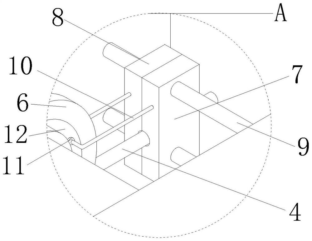
[0036] see image 3, on the basis of Embodiment 1, the left and right sides of the cable wheel 6 are provided with rotating grooves 12, and the inner walls of the two rotating grooves 12 are slidingly connected with two connecting rods 10 in the shape of an "L". The rear end of the rod 10 is inlaid with rotating balls 11, and the surfaces of the two rotating balls 11 are slidingly connected with the inner walls of the two rotating grooves 12 respectively. It is set so that the two connecting rods 10 cannot break away from the rotating groove 12, so that the two connecting rods 10 can move along with the movement of the cable arrangement wheel 6, thereby ensuring the smooth operation of the device, and the two connecting rods 10 are far away from the cable arrangement One end of wheel 6 is provided with cleaning mechanism, and cleaning mechanism comprises the first cleaning shell 8, the second cleaning shell 7, and the first cleaning shell 8 and the second cleaning shell 7 are ...


PUM


Abstract

The invention discloses a pneumatic crane, and relates to the technical field of cranes. The pneumatic crane comprises a pneumatic crane body, a fixing frame, a motor, a wire roller, a steel wire rope, a fixing rod and a wire arranging wheel, rotating grooves are formed in the left side and the right side of the wire arranging wheel correspondingly, two L-shaped connecting rods are slidably connected to the inner walls of the two rotating grooves correspondingly, and rotating balls are embedded in the rear ends of the two connecting rods correspondingly; the surfaces of the two rotating balls are slidably connected with the inner walls of the two rotating grooves correspondingly, and cleaning mechanisms are arranged at the ends, away from the wire arranging wheel, of the two connecting rods. Through the arrangement of the cleaning mechanism, rust on the steel wire rope is cleaned while the crane is used, so that an operator does not need to clean the steel wire rope additionally, the labor intensity of the operator is reduced, the burden of the operator is relieved, meanwhile, the cleaning speed of the device is the same as the speed of the steel wire rope, and the cleaning efficiency is improved. And the steel wire rope cleaning efficiency of the device is greatly improved.

Description

technical field [0001] The invention relates to the technical field of cranes, in particular to a pneumatic crane. Background technique [0002] A crane refers to a multi-action hoisting machine that lifts vertically and carries heavy objects horizontally within a certain range. Also known as cranes, cranes, cranes, etc., in the current industrial production process, product transfer and loading and unloading processes are often inseparable from cranes. Cranes are generally divided into electric, hydraulic and pneumatic types. For some specific occasions, light Cranes often adopt full pneumatic mode, among which pneumatic tower crane is a kind of tower crane. [0003] However, in the existing pneumatic tower cranes, in order to improve the wind resistance of the tower crane itself, the hoist of the pneumatic tower crane is exposed to the outside world, and when it rains outside, the rainwater will contact the wire rope on the hoist, which will cause the wire rope to rust I...

Claims


Application Information

Patent Timeline
Patent Type & Authority Applications(China)
IPC IPC(8): B66C13/00B24B27/033B24B55/12B24B41/00
CPCB66C13/00B24B27/033B24B55/12B24B41/00
Inventor 孙煌杰阮素丽朱广超严可罗叙华郑方敢
Owner SHAOXING NANTE HOISTING EQUIP CO LTD
Why Eureka
Try Eureka