Ultra-low load combustion device suitable for wall type rotational flow opposed firing boiler

A technology of opposing combustion and combustion devices, which is applied in the direction of using various fuel combustion, combustion types, combustion equipment, etc., can solve the problems of reduced load operation, etc., and achieve the effects of low load stability, low heat capacity, and environmentally friendly operation

Pending Publication Date: 2022-05-10
HARBIN BOSHEN TECH DEV CO LTD
View PDF0 Cites 0 Cited by
  • Summary
  • Abstract
  • Description
  • Claims
  • Application Information

AI Technical Summary

Problems solved by technology

However, the flexibility transformation technology of the existing wall-type swirling counter-firing boiler can realize stable operation at 40% of the rated load to the greatest extent. Due to the constraints of the current boiler technology level and equipment, the unit has no way to further reduce the load operation.

Method used


Image

  • Ultra-low load combustion device suitable for wall type rotational flow opposed firing boiler
  • Ultra-low load combustion device suitable for wall type rotational flow opposed firing boiler
  • Ultra-low load combustion device suitable for wall type rotational flow opposed firing boiler

Examples


Embodiment 1

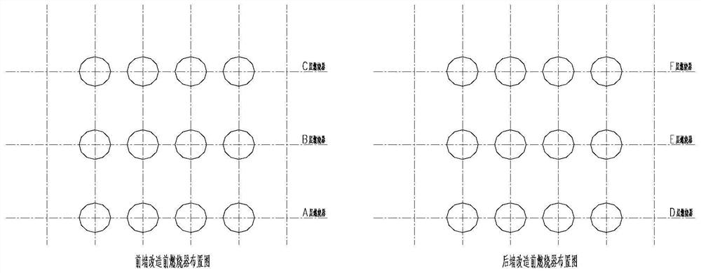
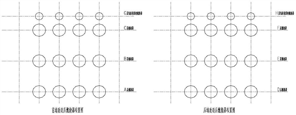
[0030] Renovate the wall-type swirling counter-fired boiler, add a layer of low-capacity pulverized coal burners (G and H) above the original uppermost layer of burners on the front and rear walls, and arrange the low-capacity pulverized coal burners on each layer The number is the same as the number of original burner arrangements on each floor. The layout position of the low-capacity pulverized coal burner is the same as that of the burner in the longitudinal direction; figure 2 (taking 4 main burners on each floor as an example) as shown.

[0031] The small-capacity pulverized coal feeding device is equipped with corresponding coal incoming, cold and hot air systems, and the low-capacity pulverized coal burner is equipped with an air box air duct and a water-cooled wall.

[0032] Wherein, the small-capacity pulverized coal feeding device communicates with the low-capacity pulverized coal burner. When the number of small-capacity pulverized coal feeding devices is 1 set, ...

Embodiment 2

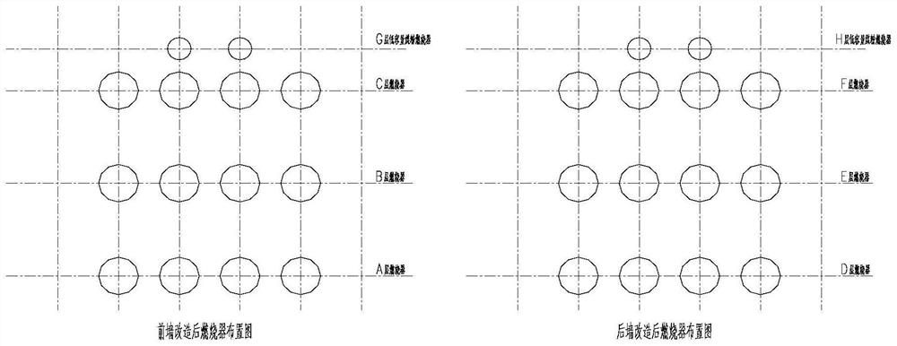
[0035] Renovate the wall-type swirling counter-combustion boiler, add a layer of low-capacity pulverized coal burners (G and H) above the original uppermost layer of burners on the front and rear walls, and the number of original burners on each layer is N , the number of low-capacity pulverized coal burners in each layer is N-2; the layout position of low-capacity pulverized coal burners is the same as that of the burners in the longitudinal direction. The arrangement of burners and low-capacity pulverized coal burners after transformation is as follows: image 3 (taking 4 main burners on each floor as an example) as shown.

[0036] The small-capacity pulverized coal feeding device is equipped with corresponding coal incoming, cold and hot air systems, and the low-capacity pulverized coal burner is equipped with an air box air duct and a water-cooled wall.

[0037] Wherein, the small-capacity pulverized coal feeding device communicates with the low-capacity pulverized coal b...

Embodiment 3

[0040] Renovate the wall-type swirling counter-combustion boiler, add a layer of low-capacity pulverized coal burners (G and H) above the original uppermost layer of burners on the front and rear walls, and the number of original burners on each layer is N , the number of low-capacity pulverized coal burners on each floor is N-1; the layout of low-capacity pulverized coal burners is vertically staggered with the burner layout. The arrangement of burners and low-capacity pulverized coal burners after transformation is as follows: Figure 4 (taking 4 main burners on each floor as an example) as shown.

[0041] The small-capacity pulverized coal feeding device is equipped with corresponding coal incoming, cold and hot air systems, and the low-capacity pulverized coal burner is equipped with an air box air duct and a water-cooled wall.

[0042] Wherein, the small-capacity pulverized coal feeding device communicates with the low-capacity pulverized coal burner. When the number of...


PUM


Abstract

The invention relates to the technical field of coal-fired boilers, in particular to an ultralow-load combustion device suitable for a wall type rotational flow opposed firing boiler. The ultra-low load combustion device comprises combustors, low-capacity pulverized coal combustors and a powder supply device, and is characterized in that a layer of low-capacity pulverized coal combustors is additionally arranged on each of the original uppermost combustors on the front wall and the rear wall of the opposed firing boiler, and the arrangement number of the low-capacity pulverized coal combustors on each layer is smaller than or equal to the arrangement number of the original combustors on each layer. According to the ultralow-load combustion device, the boiler can stably operate for a long time under 15% rated load without any auxiliary combustion-supporting means such as oil, gas, plasma and oxygen enrichment.

Description

technical field [0001] The invention relates to the technical field of coal-fired boilers, in particular to an ultra-low-load combustion device suitable for wall-type swirl-flow opposed combustion boilers. Background technique [0002] During the "14th Five-Year Plan" period, the country will vigorously develop clean and renewable energy, create conditions for carbon peaking in 2030, carbon neutrality in 2060, and ensure the reduction of fossil energy consumption, so as to achieve rapid access to the grid and stable operation of clean and renewable energy. , while maximizing the safety and stable operation of the overall power grid. Thermal power needs to undertake more and deeper peak-shaving tasks. In this case, more and more thermal power units participate in power grid peak-shaving, and truly play the role of "ballast stone" for the stable operation of the power grid. [0003] At present, thermal power units, as the main peak-shaving power source in my country, actively...

Claims


Application Information

Patent Timeline
Patent Type & Authority Applications(China)
IPC IPC(8): F23C5/28
CPCF23C5/28F23C2700/06
Inventor 牛海峰杨振国
Owner HARBIN BOSHEN TECH DEV CO LTD
Why Eureka
Try Eureka