
UV dispergation machine

A glue machine and degumming technology, applied in the manufacture of electrical components, circuits, semiconductor/solid-state devices, etc., can solve the problems of uneven degumming effect, low work efficiency, poor heat dissipation, etc., and achieve stable degumming effect. The effect of small footprint and saving loading and unloading time

Pending Publication Date: 2022-05-10
平面度科技(苏州)有限公司
View PDF0 Cites 0 Cited by
  • Summary
  • Abstract
  • Description
  • Claims
  • Application Information

AI Technical Summary

Problems solved by technology

[0004] The UV degumming machine in the prior art has the defects of low working efficiency, uneven degumming effect and poor heat dissipation

Method used


Image

  • UV dispergation machine
  • UV dispergation machine
  • UV dispergation machine

Examples


Embodiment 1

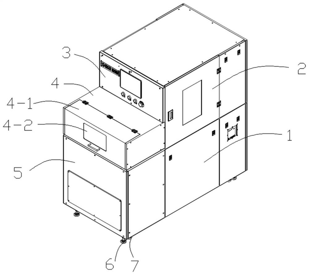
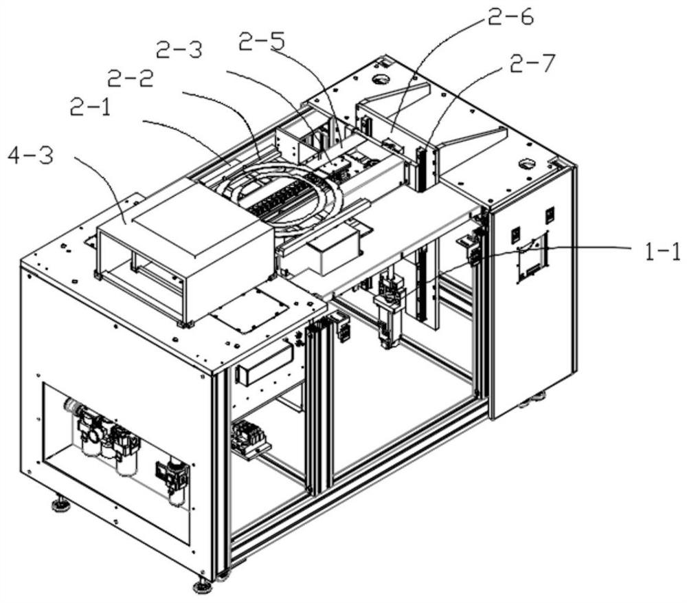
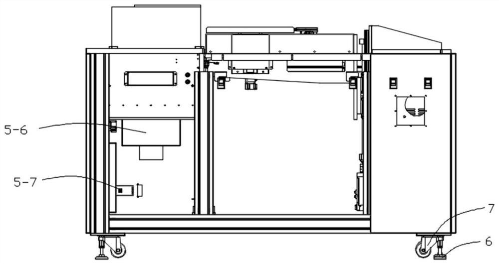
[0029] Such as Figures 1 to 4 As shown, this embodiment provides a UV dissolving machine, which includes an outer casing, a support assembly 6 and a roller assembly 7 arranged at the four corners of the bottom of the outer casing, and the outer casing includes a wafer placement box on the upper left side 4. The main basket box for placing the wafer basket on the upper right side 2. The wafer sub-box on the lower right side for lifting and lowering the wafer basket 1. The deglue box 5 for wafer debonding on the lower left side. The wafer placement box 4, the basket main box 2, the wafer sub-box 1 and the deglue box 5 are sequentially connected, and the wafer placement box 4 is provided with a wafer box 4-3 for placing wafers. The box 2 is provided with a wafer carrier 2-2, a mounting frame 2-5, an adjustment frame 2-1 which is arranged on the mounting frame 2-5 and can adjust the distance of the wafer carrier 2-2, and is arranged on the mounting frame 2-2. 5 and can move hori...

Embodiment 2

[0035] This embodiment is further optimized on the basis of embodiment 1, specifically:

[0036] A nitrogen nozzle 5-4 is arranged on the top of the degumming box 5, and an exhaust fan 5-7 is arranged on the inner bottom of the degumming box 5 to make nitrogen convective.

[0037] A cooling fan is arranged in the degumming box 5 .

[0038] The wafer box 4-3 is a U-shaped folded plate with the opening facing downwards. The width of the U-shaped folded plate is adapted to the width of the wafer basket 2-2. The wafer placement box 4 is provided with an opening. A sealing cover 4-1 is hingedly arranged at the opening, and a transparent observation window 4-2 and a handle are arranged on the sealing cover 4-1.

[0039] A control panel 3 is arranged on the left side of the main box 2 of the carrying basket, and a plurality of control buttons are arranged on the control panel 3 .

[0040] The inner right side wall of the main box 2 of the basket is provided with a vertical guide pl...


PUM


Abstract

The invention discloses a UV dispergation machine, and relates to the technical field of dispergation machines, the UV dispergation machine comprises an outer shell, and support assemblies and roller assemblies arranged at four corners of the bottom of the outer shell; the outer shell comprises a wafer placing box located on the upper left side, a basket main box located on the upper right side and used for placing a wafer basket, a wafer secondary box located on the lower right side and used for lifting the wafer basket, and a dispergation box located on the lower left side and used for dispergation of wafers, and the wafer placing box, the basket main box, the wafer secondary box and the dispergation box are sequentially communicated; a wafer box for placing a wafer is arranged in the wafer placing box, and a wafer lifting basket, a mounting rack, an adjusting rack which is arranged on the mounting rack and can adjust the distance of placing the wafer lifting basket, and a mechanical gripper assembly which is arranged on the mounting rack and can horizontally move into the wafer box along the mounting rack to pick up the wafer are arranged in the lifting basket main box; the device is reasonable in design, and has the advantages of high integration level, good peptizing effect and high working efficiency.

Description

technical field [0001] The present invention relates to the technical field of degumming machines, more specifically to the technical field of UV degumming machines. Background technique [0002] In the semiconductor chip production process, before the chip is diced, the wafer must be fixed on the frame with a dicing adhesive film. After the dicing process is completed, the fixed adhesive film is irradiated with UV light to make the UV adhesive film viscous and harden. , to reduce the viscosity of the dicing film, so that the subsequent packaging process can be smoothly produced. When ultraviolet rays are irradiated, the adhesive strength becomes lower. Therefore, the wafer or chip can be easily peeled off from the adhesive tape after being irradiated with ultraviolet rays. [0003] The UV degumming machine solves the degumming process of the wafer, glass and ceramic cutting process. The applicable industry is not limited to the semiconductor packaging industry, but also s...

Claims


Application Information

Patent Timeline
Patent Type & Authority Applications(China)
IPC IPC(8): H01L21/67H01L21/687
CPCH01L21/67132H01L21/67115H01L21/67109H01L21/68707
Inventor 解小青
Owner 平面度科技(苏州)有限公司
Learn More