Firing equipment for charcoal-fired wood processing

A technology of charcoal burning and equipment, which is applied in the direction of wood processing equipment, charcoal burning/combustion, woodworking safety devices, etc., which can solve the problems of inability to perform charcoal burning in an all-round way in a rotating manner, and achieve the effect of avoiding gas leakage and a comprehensive range

Pending Publication Date: 2022-05-13
骆思渝
View PDF7 Cites 0 Cited by
  • Summary
  • Abstract
  • Description
  • Claims
  • Application Information

AI Technical Summary

Problems solved by technology

Through the rotation of the first bracket drive roller, the second bracket drive roller, the hard steel wire wheel, the soft copper wire wheel and the linen wheel, the sheet material is transported under the hard steel wire wheel for wood grain drawing treatmen

Method used


Image

  • Firing equipment for charcoal-fired wood processing
  • Firing equipment for charcoal-fired wood processing
  • Firing equipment for charcoal-fired wood processing

Examples


Example Embodiment

[0037] Example 1

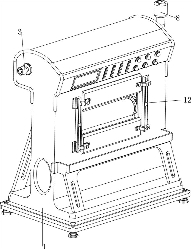
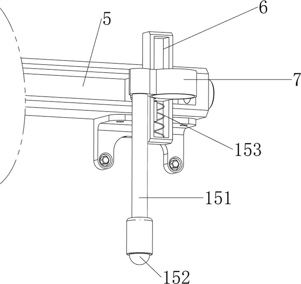
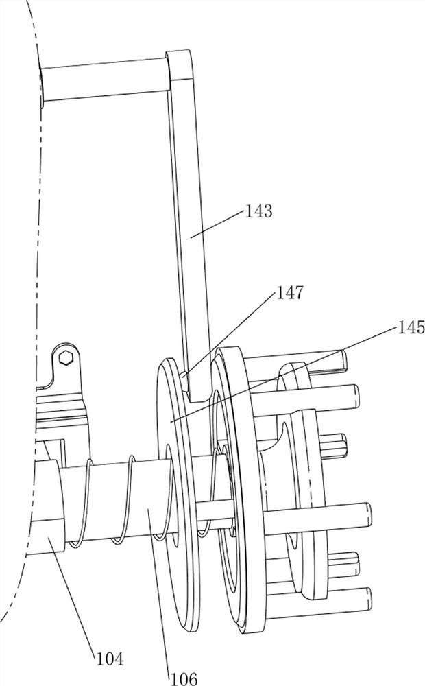
[0038] A firing equipment for charcoal burning wood processing, such as figure 1 , figure 2 , image 3 and Figure 4As shown, it includes a frame body 1, a first bracket 2, an air tank 3, a hose 4, a first slide rail 5, a second slide rail 6, a spray gun 7, a smoke exhaust pipe 8, a valve 9, and a rotating mechanism 10 and the drive mechanism 11, the front side of the frame body 1 is provided with a discharge port, the upper left and right sides of the frame body 1 are provided with first brackets 2, and the gas storage box 3 is installed between the first brackets 2 by means of bolts. The left side of the gas box 3 is provided with a box cover, the right end of the gas storage box 3 is provided with a hose 4, and the upper part of the frame body 1 is provided with a first slide rail 5, the first slide rail 5 is located at the front and bottom of the gas storage box 3, and the first slide rail 5 The right side of the rail 5 is slidingly provided with a ...

Example Embodiment

[0042] Example 2

[0043] On the basis of Example 1, such as figure 1 , Figure 8 , Figure 9 and Figure 10 As shown, a protection mechanism 12 is also included, and the protection mechanism 12 includes a fourth slide rail 121, a baffle plate 122, a third bracket 123, a space cam 124, a first torsion spring 125, a contact block 126, a second gear 127, a first A sliding sleeve 128, the first pushing block 129 and the second spring 1210, the left and right sides of the front part of the frame body 1 are provided with a fourth slide rail 121, and the upper and lower parts of the fourth slide rail 121 are slidably connected with a The baffle plate 122 of the material discharge port is provided with a third bracket 123 on the right side of the front upper part of the frame body 1, and a space cam 124 is installed between the third bracket 123 and the frame body 1 through a bearing, and the right side of the rear portion of the baffle plate 122 All are in sliding contact with t...


PUM


Abstract

The invention relates to firing equipment, in particular to firing equipment for charcoal-fired wood processing. The invention provides firing equipment for processing charcoal-fired wood, and the firing equipment is in a rotary all-dimensional charcoal-fired mode. A burning device for charcoal burning wood processing comprises a frame body, first supports, a gas storage box, a hose, a first sliding rail, a second sliding rail, a flame gun, a smoke exhaust pipe and the like, the first supports are arranged on the left side and the right side of the upper portion in the frame body, the gas storage box is installed between the first supports, and the hose is arranged at the right end of the gas storage box; a first sliding rail located below the front portion of the gas storage box is arranged on the upper portion in the frame body, a second sliding rail is slidably arranged on the right side of the first sliding rail, a flame gun is slidably installed on the second sliding rail, the top of the flame gun is connected with a hose, and a smoke exhaust pipe is arranged on the upper right portion of the frame body. The flame gun can intermittently move leftwards, so that wood is uniformly charred from right to left, and when the flame gun pauses, the flame gun performs timing flame-jet charring on the rotating wood, so that the wood can be thoroughly charred.

Description

technical field [0001] The invention relates to a firing equipment, in particular to a firing equipment for charcoal burning wood processing. Background technique [0002] Charcoal-fired wood is a wood manufacturing process that evenly burns a thin carbonized layer on the surface of wood, so that the wood has the characteristics of anti-corrosion and insect-proof. Charcoal-fired wood can well highlight the uneven and three-dimensional wood grain on the surface of the wood. Improves the aesthetics of wood. [0003] Patent application CN202241517U, with a publication date of 20120530, discloses a charcoal-burning wood processing device, including a frame, a workbench, a transmission roller, a transmission chain, a transmission sprocket, a lifting adjustment screw, a sliding support rod, a bracket, a motor, and a sprocket , cover, hard steel wire wheel, fire baffle, mixed gas nozzle, soft copper wire wheel and linen wheel, the workbench is installed on the frame, and evenly di...

Claims


Application Information

Patent Timeline
IPC IPC(8): B27M1/06B27G21/00
CPCB27M1/06B27G21/00
Inventor 骆思渝
Owner 骆思渝
Why Eureka
Try Eureka