
Automatic biological reader

A reader and biological technology, which is applied in the field of biological readers for detecting and evaluating the sterilization effect of biological indicators, can solve the problems of waste, inability to automatically identify and confirm, and inability to automatically identify, save energy and increase temperature. The speed and uniformity of heat preservation, and the effect of solving uneven heating

Pending Publication Date: 2022-05-13
成都蓝峰科技有限公司
View PDF10 Cites 0 Cited by
  • Summary
  • Abstract
  • Description
  • Claims
  • Application Information

AI Technical Summary

Problems solved by technology

[0008] There are usually multiple test holes on the biological reader, so that multiple biological indicators can be placed at the same time and multiple biological indicators can be detected at the same time to improve efficiency, as disclosed in the Chinese patent document with the application number CN2021204886394 A wireless portable biological reader for medical sterilization verification, as well as the biological reader disclosed in the Chinese patent document with the application number CN201811410494.5, both have multiple test holes and can place multiple biological indicators at the same time. After a plurality of biological indicators are inserted into each test hole, the biological readers of the prior art cannot automatically identify and confirm whether there is a biological indicator inserted or correctly inserted in each test well, for example, even if there is no biological indicator in some test wells. Insert the biological indicator, the existing biological reader can not automatically identify, and all the test wells will be monitored at the same time when still in use, so that the empty slots without the biological indicator are also monitored and analyzed, causing a certain degree of waste of

Method used


Image

  • Automatic biological reader
  • Automatic biological reader
  • Automatic biological reader

Examples


Embodiment Construction

[0043] The technical solutions of the present invention are further described in detail below with reference to the accompanying drawings, but the protection scope of the present invention is not limited to the following.

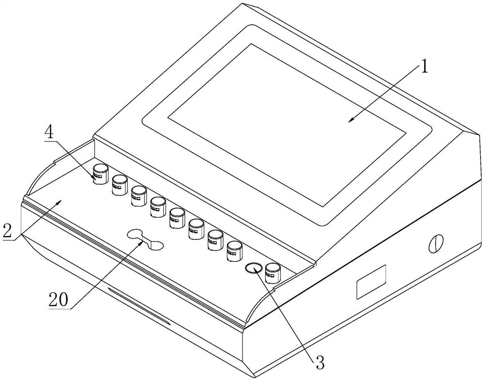
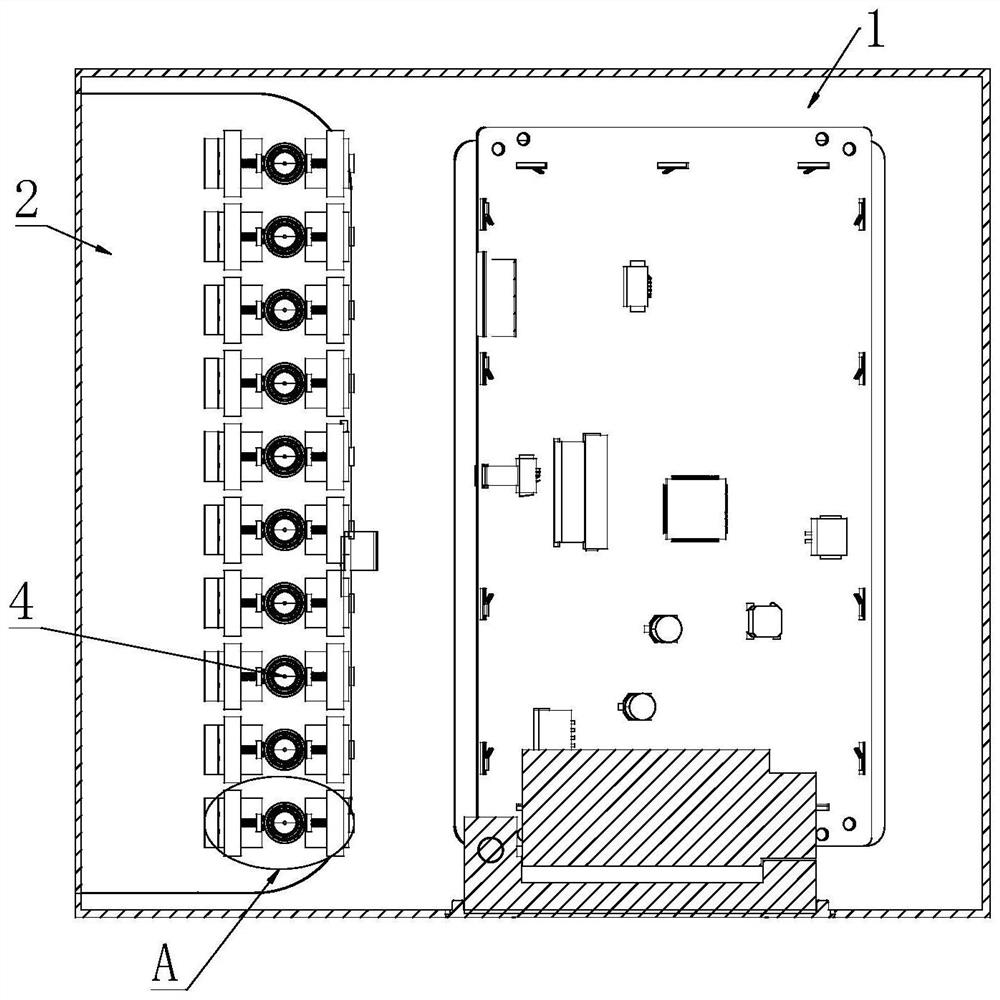
[0044] see Figure 1 to Figure 8 As shown, an automatic biological reader includes a main body 1 and a support plate 2. The main body 1 is in the shape of a casing, including an upper casing and a bottom plate, and a light source, a light receiving device, a heating device, a power supply and a control device are installed in the main body 1. A display screen is installed on the top of the main body 1 to display the detection results of the biological reader. The light source, the light receiving device, the heating device, and the display screen are all electrically connected to the controller, which are in the prior art and will not be repeated here.

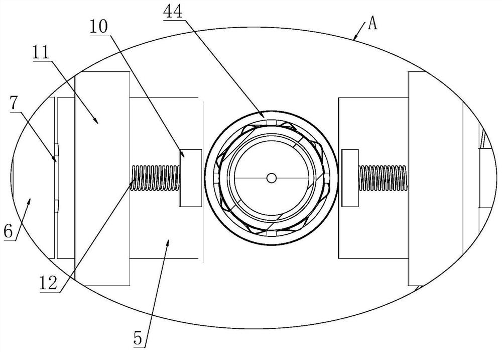
[0045] like figure 1 As shown, the support plate 2 is installed on one side of the top of the main bo...


PUM


Abstract

The invention discloses an automatic biological reader which comprises a body and a supporting plate, a placing frame is installed below the supporting plate, a plurality of placing pipe grooves are formed in the placing frame, a heating device and a controller are installed in the body, and the heating device comprises an electric heating piece and a temperature detector. The electric heating sheets are respectively arranged at the upper half part and the lower half part of the semi-circumferential side wall of each placing pipe groove; a temperature detector is arranged at the upper half part or the lower half part of the other side, opposite to the electric heating sheets, of each placing pipe groove; a movable plate and a reader are arranged at the position, corresponding to each pipe containing groove, below the supporting plate, a magnetic card is arranged on the movable plate, the movable plate can drive the magnetic card to move towards the reader, and after the reader reads information of the magnetic card, the information can be transmitted to a controller; the controller can judge whether the biological indicator is inserted into the placing pipe groove or not according to the received information, the inserted biological indicator is subjected to heating culture and detection, and the placing pipe groove without the biological indicator is not subjected to heating and detection.

Description

technical field [0001] The invention relates to the technical field of biological reagent detection, in particular to a biological reader for detecting and evaluating the sterilization effect of biological indicators. Background technique [0002] The biological reader is mainly used to interpret the inactivation of biological indicators and to monitor the sterilization effect of the sterilizer. [0003] Existing medical disinfection and sterilization equipment, whether it is used for low-temperature sterilization, such as hydrogen peroxide low-temperature plasma sterilizer, or high-temperature sterilization, such as pulsating vacuum pressure steam sterilizer, should be In order to evaluate the sterilization effect of medical devices in the sterilizer when the medical devices are put into the sterilization chamber of the sterilizer for sterilization, it is usually necessary to add a biological indicator containing specific bacteria together with the sterilizer to be steriliz...

Claims


Application Information

Patent Timeline
Patent Type & Authority Applications(China)
IPC IPC(8): C12M1/38C12M1/36C12M1/34C12M1/24C12M1/02C12M1/00G01N21/64
CPCC12M23/08C12M23/38C12M23/46C12M23/48C12M41/12C12M41/22C12M41/36C12M41/48G01N21/6486
Inventor 陈书明
Owner 成都蓝峰科技有限公司
Learn More