Functional security chip and working method thereof

A functional safety, chip technology, applied in program control, instrumentation, computer control, etc., can solve the problems of complex design, difficult maintenance, and high cost, and achieve the effect of reducing overall cost, reducing the number of components, and improving consistency

Pending Publication Date: 2022-05-13
CRRC QINGDAO SIFANG ROLLING STOCK RES INST
View PDF0 Cites 0 Cited by
  • Summary
  • Abstract
  • Description
  • Claims
  • Application Information

AI Technical Summary

Problems solved by technology

[0005] The present invention aims at technical problems such as complex design, large volume, high cost, and difficult maintenance in the above-mentioned electronic control system controlled by multiple CPUs, and proposes a functional safety chip with small size and easy development and its working method

Method used


Image

  • Functional security chip and working method thereof
  • Functional security chip and working method thereof
  • Functional security chip and working method thereof

Examples


Embodiment 1

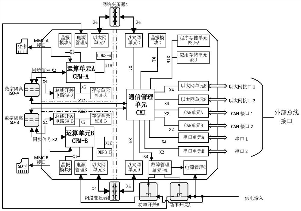
[0050] figure 1 It is a schematic diagram of the internal structure of a functional safety chip provided by the present invention. like figure 1 As shown, the functional safety chip FSC contains 2 computing units: computing unit CPM-A, computing unit CPM-B; 1 communication management unit CMU; 4 storage units: program storage unit PSU-A, application storage unit ASU, Storage unit MEM-A, storage unit MEM-B; 2 DDR3 modules: DDR3-A, DDR3-B; 3 power management units: power management A, B, C; 2 bus switch circuits: bus switch circuit SW- A. Bus switch circuit SW-B; 1 fault management unit FMU; 3 crystal oscillator modules: crystal oscillator modules A, B, C; 6 Ethernet interface units: Ethernet units A, B, C, D, E, F ; 2 CAN interface units: CAN unit A, B; 2 serial port interface units: serial port unit A, B.

[0051] Among them, the main function of the calculation unit (CPM) is calculation processing, and the functions of CPM-A and CPM-B are exactly the same, and the two calc...

Embodiment 2

[0083] In combination with the functional safety chip disclosed in the first embodiment, this embodiment discloses a specific implementation example of a working method of the functional safety chip (hereinafter referred to as "method").

[0084] refer to Figure 5 As shown, the method includes:

[0085] Step S1: The communication management unit is powered on, and the communication management unit reads the executable code of the communication management unit from the program storage unit;

[0086] Step S2: After the start-up of the communication management unit is completed, the operation unit is powered on, and by making the chip select signal of the operation unit a low-level signal, the operation unit reads the executable code from the operation storage unit through the SPI bus, The computing unit starts to start;

[0087] Step S3: After the operation unit is started, the first operation unit and the second operation unit in the operation unit receive the synchronizatio...


PUM


Abstract

The invention discloses a functional security chip and a working method thereof, and the functional security chip comprises an arithmetic unit which is used for carrying out arithmetic processing on received information; the communication management unit is connected with the operation unit through an Ethernet bus and an SPI (Serial Peripheral Interface) bus, and the communication management unit is used for receiving external information through an external bus interface, sending the information to the operation unit through the Ethernet bus, receiving a periodic operation result output by the operation unit and comparing and analyzing the periodic operation result; and the fault management unit is connected with the communication management unit, the communication management unit sends state signals of the communication management unit and the arithmetic unit to the fault management unit, and the fault management unit controls power-on and power-off of the arithmetic unit and the communication management unit through the power management unit according to the state signals. The functional security chip provided by the invention is a security chip which is small in size and easy to develop and maintain.

Description

technical field [0001] The invention relates to the field of security chip design, in particular to a functional security chip and a working method thereof. Background technique [0002] In recent years, security technology in the field of electronic control has developed rapidly, among which information security technology and functional safety technology have attracted much attention. [0003] In the control fields of rail transit, automobiles, and nuclear power, the functional safety of the control system is very important. If there are serious defects in the design of the control system, it will cause major accidents such as personal and property losses and environmental hazards. Therefore, in these key control areas, product safety design technology is very important. It is necessary to carry out electronic control system design according to industry functional safety standards, and must pass the corresponding functional safety certification. [0004] Traditional high-...

Claims


Application Information

Patent Timeline
IPC IPC(8): G05B19/042
CPCG05B19/0423G05B2219/24215Y02D10/00
Inventor 李震姚小强王凯赵晟禹
Owner CRRC QINGDAO SIFANG ROLLING STOCK RES INST
Why Eureka
Try Eureka