
Flue gas desulfurization system

A desulfurization system and flue gas technology, applied in gas treatment, separation methods, products, etc., can solve problems such as poor tail gas treatment results and increased greenhouse gas emissions, so as to improve flue gas treatment results, achieve low carbon emissions, and facilitate The effect of promotional use

Pending Publication Date: 2022-05-17
广东能源集团科学技术研究院有限公司
View PDF0 Cites 0 Cited by
  • Summary
  • Abstract
  • Description
  • Claims
  • Application Information

AI Technical Summary

Problems solved by technology

In the upper oxidation zone, oxidizing air is blown in through a distribution system to generate gypsum in a slurry with a pH value of 4.5 to 5.5; in the crystallization zone, the gypsum crystal seeds gradually increase and form larger crystals that are easy to dehydrate. New limestone slurry was also added to this area, the overall chemical reaction formula: CaCO 3 +SO 2 +1 / 2O 2 +2H 2 O→CaSO 4 2H 2 O+CO 2 , it can be seen from the chemical reaction process that in the removal of SO 2 process, will generate CO 2 , increased greenhouse gas emissions, and poor tail gas treatment results

Method used


Image

  • Flue gas desulfurization system

Examples


Embodiment Construction

[0018] The specific implementation manners of the present invention will be further described in detail below in conjunction with the accompanying drawings and embodiments. The following examples are used to illustrate the present invention, but are not intended to limit the scope of the present invention.

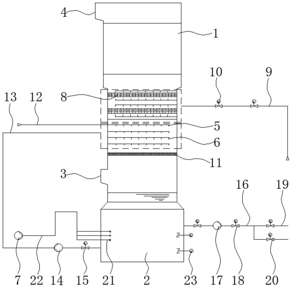
[0019] Such as figure 1 As shown, a flue gas desulfurization system according to a preferred embodiment of the present invention includes a tower body 1, the bottom of the tower body 1 is provided with a liquid storage chamber 2 for storing limestone solution, and the side wall of the tower body 1 A flue gas inlet 3 is provided, a first spray layer 5 and a second spray layer 6 are provided inside the tower body 1, and an exhaust port 4 is provided on the top of the tower body 1 for discharging desulfurized Clean smoke. The first spray layer 5 and the second spray layer 6 are located between the flue gas inlet 3 and the exhaust port 4, and the first spray layer 5 is used ...


PUM


Abstract

The present invention relates to the technical field of flue gas desulfurization, and discloses a flue gas desulfurization system, which comprises a tower body, the bottom of the tower body is provided with a liquid storage cavity for storing a limestone solution, the side wall of the tower body is provided with a flue gas inlet, the tower body is internally provided with a first spraying layer and a second spraying layer, the top of the tower body is provided with an exhaust port, and the top of the tower body is provided with a gas outlet. The first spraying layer and the second spraying layer are located between the flue gas inlet and the exhaust port, the first spraying layer is used for spraying a calcium hydroxide solution, the second spraying layer is communicated with the liquid storage cavity, and the side wall of the liquid storage cavity is connected with an oxidation fan and a gypsum discharge assembly. According to the desulfurization tower, the first spraying layer and the second spraying layer are arranged in the tower body, the first spraying layer is used for spraying a calcium hydroxide solution, and the second spraying layer is communicated with the liquid storage cavity, so that no carbon dioxide is discharged in the whole desulfurization process, low carbon emission in the absorption process is realized, and the flue gas treatment result is improved.

Description

technical field [0001] The invention relates to the technical field of flue gas desulfurization, in particular to a flue gas desulfurization system. Background technique [0002] Existing thermal power group flue gas desulfurization projects usually use limestone-gypsum wet flue gas desulfurization process, and the desulfurization efficiency guarantee value of the desulfurization device is greater than 93%. One furnace and one tower system is adopted. The FGD unit adopts wet forced oxidation and limestone-gypsum recovery process. However, for the removal of SO 2 The slurry is collected in the absorption tower slurry tank, which is divided into oxidation zone and crystallization zone. In the upper oxidation zone, oxidizing air is blown in through a distribution system to generate gypsum in a slurry with a pH value of 4.5 to 5.5; in the crystallization zone, the gypsum crystal seeds gradually increase and form larger crystals that are easy to dehydrate. New limestone slurr...

Claims


Application Information

Patent Timeline
Patent Type & Authority Applications(China)
IPC IPC(8): B01D53/75B01D53/79B01D53/80B01D53/50B01D53/96
CPCB01D53/75B01D53/79B01D53/80B01D53/502B01D53/96B01D2251/404B01D2251/604B01D2251/606B01D2258/0283Y02P20/151
Inventor 黎石竹姚勇陈创庭吴志超郭映嘉饶睦敏于驰
Owner 广东能源集团科学技术研究院有限公司
Learn More