
Detection method for dielectric property of ceramic powder and application of detection method

A technology for ceramic powder and dielectric properties, which is applied in the field of functional material testing, can solve the problems of difficulty in meeting the requirements of high-frequency dielectric materials, low Df test accuracy, low relative dielectric constant, etc., and achieves a simple sample preparation process. Effective, small error, small size effect

Pending Publication Date: 2022-05-17
SHANDONG SINOCERA FUNCTIONAL MATERIAL CO LTD
View PDF6 Cites 0 Cited by
  • Summary
  • Abstract
  • Description
  • Claims
  • Application Information

AI Technical Summary

Problems solved by technology

However, there are very few polar groups in the molecular structure of PTFE, resulting in low relative permittivity (Dk10)
In order to improve the dielectric constant and mechanical properties of PTFE copper clad laminates, it is usually reinforced and modified by compounding high dielectric ceramic powder or glass fiber cloth. Since the detection method of ceramic powder such as strip line needs to make a variety of resonant circuit chips of different specifications , and the Df test accuracy is low, so it is not suitable for the rapid detection and application evaluation of high dielectric ceramic powder filled with PTFE copper clad laminates

Method used


Image

  • Detection method for dielectric property of ceramic powder and application of detection method
  • Detection method for dielectric property of ceramic powder and application of detection method

Examples


Embodiment 1

[0029] This embodiment provides a method for detecting the dielectric properties of ceramic powder, the specific steps are as follows:

[0030] S1. Titanium dioxide powder (particle size is 20 μm, spherical shape, impurity content <1wt%) and dispersed PTFE resin (particle size is 10 μm) are added to the high-speed mixer at a mass ratio of 10:5, and the mixture is evenly mixed at a stirring rate of 8000 rpm. Disperse and mix for 120s, set aside;

[0031] S2. Transfer the homogeneously mixed materials into a mixing container, add titanium dioxide and petroleum ether with a total mass of 25% of PTFE resin, stir quickly until it is in the shape of "bread crumbs", and seal it for later use;

[0032] S3, aging the material of S2 at room temperature for 20 minutes;

[0033] S4, the material of S3 is rolled into a sheet-like sample of PTFE / titanium dioxide / petroleum ether through a film rolling machine with a rotating speed of 9 rpm and a roll spacing of 0.6 μm;

[0034] S5, put the...

Embodiment 2

[0039] The difference between the testing method for the dielectric properties of the ceramic powder provided in this example and Example 1 is that the mixing time in step S1 is 0 s, that is, the PTFE resin does not undergo dispersion treatment.

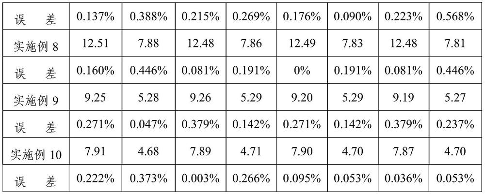
[0040] After testing, at room temperature, the sample density is 3.015g / cm 3 , The dielectric constant is 10.45 at 10GHz, and the dielectric loss is 0.000715.

Embodiment 3

[0042] The difference between the detection method provided in this example and Example 1 is that the forming agent in step S2 is aviation kerosene.

[0043] After testing, at room temperature, the sample density is 2.868g / cm 3 , The dielectric constant is 8.99 at 10GHz, and the dielectric loss is 0.000675.


PUM

PropertyMeasurementUnit
particle diameteraaaaaaaaaa
densityaaaaaaaaaa

Abstract

The invention provides a method for detecting the dielectric property of ceramic powder and application thereof, the method for detecting the dielectric property of the ceramic powder comprises sample preparation and detection, and the sample preparation comprises the following steps: mixing ceramic powder, polytetrafluoroethylene and a forming agent, curing, calendaring, degumming, sintering and curing to obtain a to-be-detected prepreg. The detection method provided by the invention can accurately determine the dielectric property of the ceramic powder filled in polytetrafluoroethylene, and can be used for evaluating the dielectric property of pure ceramic powder or a composite material of the ceramic powder and the like. The detection method provided by the invention is accurate in detection, small in error and fast in time efficiency.

Description

technical field [0001] The invention relates to the detection field of functional materials, in particular to a detection method for the dielectric properties of ceramic powder and its application. Background technique [0002] The development of wireless communication technology in the direction of high frequency and high speed has led to high integration, miniaturization and high stability of modules such as baseband circuits and radio frequency antennas, and the size of the device is inversely proportional to the relative dielectric constant of the substrate. Therefore, printed circuit boards The substrate (copper clad laminate, CCL) needs to have high dielectric constant and low dielectric loss characteristics, which puts forward very strict requirements on the performance of the substrate. [0003] Due to the special helical conformation molecular structure, polytetrafluoroethylene (PTFE) has extremely excellent dielectric properties (dielectric loss Df is 0.0001, which...

Claims


Application Information

Patent Timeline
Patent Type & Authority Applications(China)
IPC IPC(8): G01N27/22G01R27/26G01N1/28G01N1/38
CPCG01N27/221G01R27/2617G01R27/2635G01N1/28G01N1/286G01N1/38
Inventor 朱恒李忠国马艳青窦玲徐姗姗刘金祥
Owner SHANDONG SINOCERA FUNCTIONAL MATERIAL CO LTD
Learn More