Voltage stabilizer circuit and electronic equipment
A voltage stabilizer and reference voltage circuit technology, applied in the direction of instruments, adjusting electrical variables, climate sustainability, etc., can solve the problems of high power consumption, increased power consumption, and affecting power-on speed, etc., to achieve small area and noise, Effect of Reducing Standby Power Consumption and Cost
- Summary
- Abstract
- Description
- Claims
- Application Information
AI Technical Summary
Problems solved by technology
Method used
Image

Examples
Embodiment 1
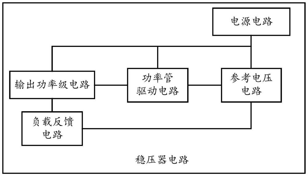
[0037] see figure 1 , figure 1 This is a schematic structural diagram of a voltage regulator circuit disclosed in an embodiment of the present invention, and the circuit can be applied to any load that needs to be regulated, which is not limited in the embodiment of the present invention. like figure 1 As shown, the voltage regulator circuit includes a power supply circuit, a reference voltage circuit, a power tube drive circuit, an output power stage circuit and a load feedback circuit, wherein:
[0038] The first end of the power supply circuit is electrically connected to the first end of the reference voltage circuit, the first end of the power tube drive circuit is electrically connected to the first end of the output power stage circuit; the second end of the reference voltage circuit is electrically connected to the first end of the power tube drive circuit. The second terminal is electrically connected; the third terminal of the reference voltage circuit is electrica...
Embodiment 2
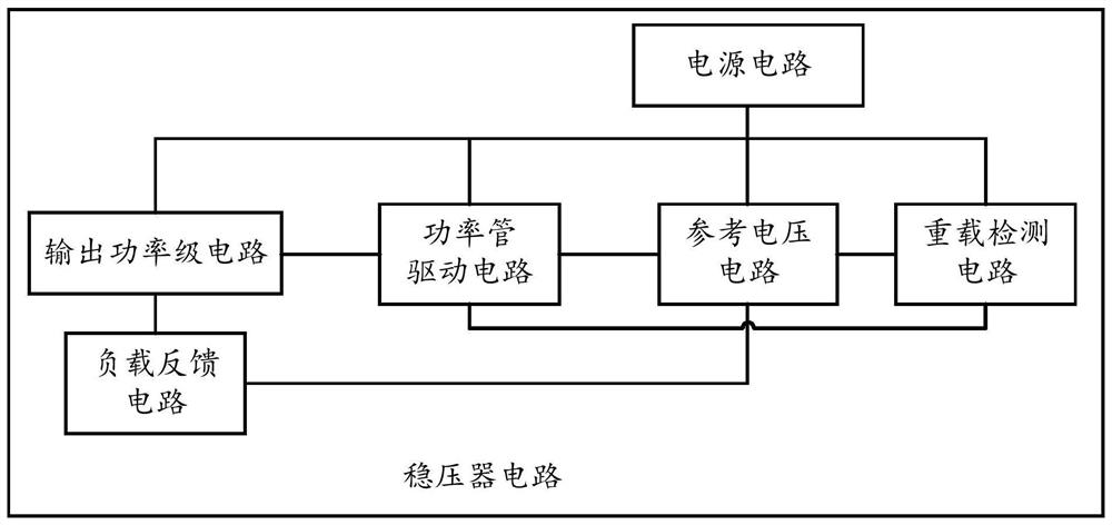
[0050] see figure 2 shown, as figure 2 shown, figure 2 is a schematic structural diagram of another voltage stabilizer circuit disclosed in the embodiment of the present invention, such as figure 2 As shown, the voltage stabilizer circuit includes a power supply circuit, a reference voltage circuit, a power tube drive circuit, an output power stage circuit and a load feedback circuit, wherein the voltage stabilizer circuit further includes a heavy load detection circuit;
[0051] The first end of the overload detection circuit is electrically connected to the first end of the power supply circuit; the second end of the overload detection circuit is electrically connected to the second end of the reference voltage circuit; the third end of the overload detection circuit is electrically connected to the power tube driving circuit The fifth terminal is electrically connected; the fourth terminal of the overload detection circuit is used for grounding;
[0052] The heavy-lo...
Embodiment 3
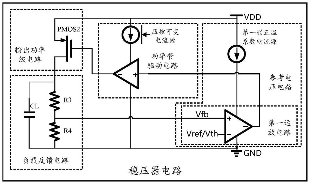
[0066] see image 3 shown, image 3 is a schematic structural diagram of another voltage stabilizer circuit disclosed in the embodiment of the present invention, such as image 3 As shown, the voltage regulator circuit includes a power supply circuit, a reference voltage circuit, a power tube drive circuit, an output power stage circuit and a load feedback circuit, wherein the reference voltage circuit includes a first operational amplifier circuit and a first weak positive temperature coefficient current source;
[0067] The first end of the first weak PTC current source is electrically connected to the first end of the power supply circuit; the second end of the first weak PTC current source is electrically connected to the first end of the first operational amplifier circuit; the third The second end of an operational amplifier circuit is electrically connected to the second end of the power tube drive circuit; the third end of the first operational amplifier circuit is e...
PUM
 Abstract
Description
Claims
Application Information
 - R&D
- Intellectual Property
- Life Sciences
- Materials
- Tech Scout
- Unparalleled Data Quality
- Higher Quality Content
- 60% Fewer Hallucinations
Browse by: Latest US Patents, China's latest patents, Technical Efficacy Thesaurus, Application Domain, Technology Topic, Popular Technical Reports.
© 2025 PatSnap. All rights reserved.Legal|Privacy policy|Modern Slavery Act Transparency Statement|Sitemap|About US| Contact US: help@patsnap.com