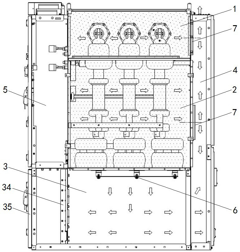
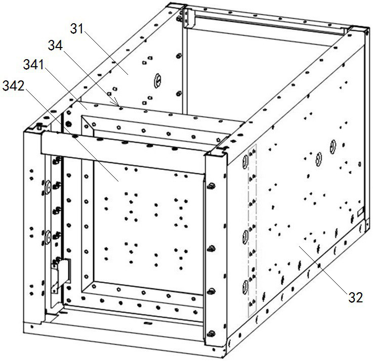
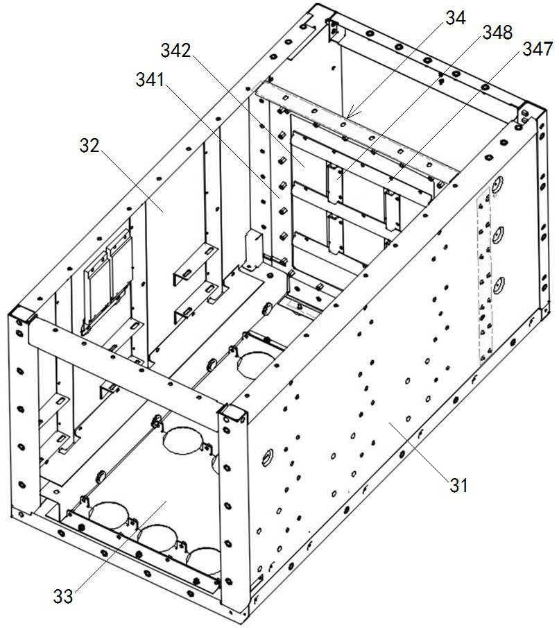
Cable chamber sealing plate assembly, cable chamber and gas insulated switchgear

A cable room and sealing plate technology, which is applied to electrical components, substation/distribution device casings, connecting components, etc., can solve the problems of heavy installation and maintenance workload, easy to be broken by high-pressure airflow, and troublesome operation, so as to reduce installation and maintenance. Work load, convenient installation and maintenance operations, and the effect of improving work efficiency

Pending Publication Date: 2022-05-24
PINGGAO GRP
View PDF3 Cites 0 Cited by
  • Summary
  • Abstract
  • Description
  • Claims
  • Application Information

AI Technical Summary

Problems solved by technology

[0008] The purpose of the present invention is to provide a cable room sealing plate assembly to solve the problem that the existing cable room sealing plate has limited structural strength and is easily broken by high-pressure airflow, causing the front door of the cable room to be opened or even collapsed, endangering the safety of equipment and personnel. At the same time, it also solves the problem that the air box must be removed first when the existing cable room sealing plate is disassembled, which leads to troublesome operation and heavy installation and maintenance workload; the purpose of the present invention is also to provide a Cable rooms and gas cabinets

Method used


Image

  • Cable chamber sealing plate assembly, cable chamber and gas insulated switchgear
  • Cable chamber sealing plate assembly, cable chamber and gas insulated switchgear
  • Cable chamber sealing plate assembly, cable chamber and gas insulated switchgear

Examples


Embodiment Construction

[0071] In order to make the objectives, technical solutions and advantages of the present invention clearer, the present invention will be further described in detail below with reference to the accompanying drawings and embodiments. It should be understood that the specific embodiments described herein are only used to explain the present invention, but not to limit the present invention, that is, the described embodiments are only a part of the embodiments of the present invention, rather than all the embodiments. The components of the embodiments of the invention generally described and illustrated in the drawings herein may be arranged and designed in a variety of different configurations.

[0072] Thus, the following detailed description of the embodiments of the invention provided in the accompanying drawings is not intended to limit the scope of the invention as claimed, but is merely representative of selected embodiments of the invention. Based on the embodiments of t...


PUM


Abstract

The invention relates to the technical field of gas insulation switch devices, in particular to a cable chamber sealing plate assembly, a cable chamber and a gas insulated switchgear, the cable chamber sealing plate assembly comprises a fixed sealing plate and a detachable sealing plate, and the left side and the right side of the fixed sealing plate are provided with side connecting edges fixedly connected with the left side plate and the right side plate of the cable chamber respectively; a top connecting edge is arranged at the top of the fixed sealing plate, a stud through hole is formed in the top connecting edge, and an access hole is further formed in the fixed sealing plate; the detachable sealing plate is detachably connected with the fixed sealing plate through a fastener and blocks the access hole, and a first reinforcing structure is arranged on the detachable sealing plate. The structural strength of the cable chamber sealing plate assembly is improved, damage of arcing or high-energy electric arcs on a cabinet body cable chamber front door and personnel around equipment under unexpected conditions is reduced to the maximum extent, and the problem that CT and incoming and outgoing cables are inconvenient to install and maintain in mainstream environment-friendly gas-insulated switchgear products in the market is solved; and the overhaul, maintenance and replacement time of an operator on an electric device under the condition of power failure operation is greatly shortened.

Description

technical field [0001] The invention relates to the technical field of gas-insulated switchgear, in particular to a cable room sealing plate assembly, a cable room and an inflatable cabinet. Background technique [0002] As an important part of the power distribution system, the environmentally friendly inflatable cabinet mainly uses dry air as the insulating medium. compared to SF 6 Inflatable cabinet, dry air inflatable cabinet completely cancels SF in the structure principle 6 Gas is more friendly to the environment. Compared with the air metal-enclosed switchgear of the same voltage level, the dry air inflatable cabinet has the advantages of good insulation performance and maintenance-free, and is more and more favored by the market. [0003] Common inflatable cabinets on the market, such as the air-insulated fixed cabinet disclosed in the patent document with the authorization announcement number CN208241178U, include a fixed cabinet shell, and the fixed cabinet shel...

Claims


Application Information

Patent Timeline
Patent Type & Authority Applications(China)
IPC IPC(8): H02B1/26H02B13/00F16B5/02
CPCH02B1/26H02B13/00F16B5/02Y02E10/72
Inventor 张庆飞卢留洋费翔袁端磊孙河南朱志豪马明乐郭锋韦磊庞健朱启媛
Owner PINGGAO GRP
Why Eureka
Try Eureka