
Bionic visual sensor with enhanced end side contour

A vision sensor and contour enhancement technology, applied in the field of bionic vision sensors, can solve the problems of unable to achieve self-adaptation, no imaging unit information transmission, exchange, unable to achieve retina contour extraction, convolution calculation, etc., to reduce data redundancy, High-resolution imaging, effects that add complexity

Active Publication Date: 2022-05-24
ZHEJIANG LAB
View PDF10 Cites 0 Cited by
  • Summary
  • Abstract
  • Description
  • Claims
  • Application Information

AI Technical Summary

Problems solved by technology

However, this design is an enhancement to multiple image training, and cannot achieve an adaptive function
[0010] In summary, the current imaging sensors focus on the processing of signal transmission in the vertical direction, and there is no technical solution for information transmission and exchange between imaging units, and it is impossible to achieve functions such as retinal contour extraction and convolution calculation similar to biological vision.

Method used


Image

  • Bionic visual sensor with enhanced end side contour
  • Bionic visual sensor with enhanced end side contour
  • Bionic visual sensor with enhanced end side contour

Examples


Embodiment Construction

[0051] Reference will now be made in detail to the exemplary embodiments, examples of which are illustrated in the accompanying drawings. When the following description refers to the accompanying drawings, the same numerals in different drawings refer to the same or similar elements unless otherwise indicated. The implementations described in the following exemplary embodiments do not represent all implementations consistent with this application. Rather, they are merely examples of apparatuses and methods consistent with aspects of the present application as recited in the appended claims.

[0052] The terminology used in this application is for the purpose of describing particular embodiments only, and is not intended to limit the application.

[0053] As used in this application and the appended claims, the singular forms "a", "the", and "the" are intended to include the plural forms as well, unless the context clearly dictates otherwise. It should also be understood that...


PUM


Abstract

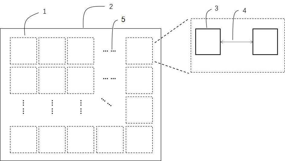
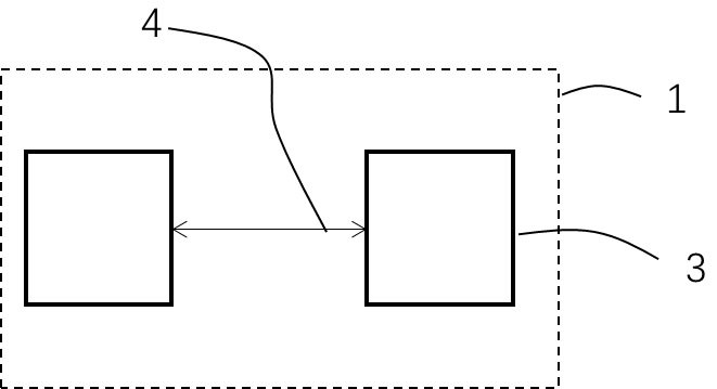
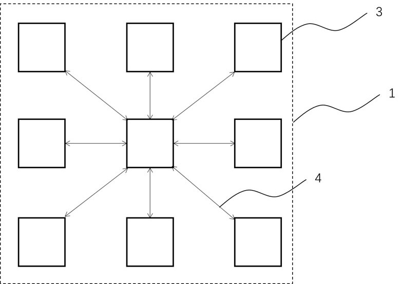
The invention discloses a bionic visual sensor with an enhanced end side contour, and the sensor comprises a sensor main body element module which comprises one or more pixels, each pixel comprises a plurality of elements which are used for converting an optical signal into an electric signal, and the elements in each pixel have a light intensity information exchange capability, the sensitivity of the elements is regulated and controlled through light intensity information exchange, the light intensity difference between the elements is amplified, and the purpose of outline enhancement is achieved. The visual sensor is based on a lateral inhibition function of horizontal cells in a human retina, and on the basis of image acquisition, end-side contour enhancement and image feature extraction can be achieved on the hardware level through an antagonism effect between elements in pixels, so that information redundancy is reduced, the imaging speed is increased, and the imaging precision is improved. And self-adaption and self-regulation are realized, and manual regulation is not needed.

Description

technical field [0001] The invention relates to the field of neuromorphic intelligent visual sensing, in particular to a bionic visual sensor with end-side contour enhancement. Background technique [0002] The vision sensor is the core photosensitive element of the camera, the cornerstone of the Internet of Things, and the basis for the future intelligence of the manufacturing industry. The vision sensor is the direct source of information for the entire machine vision system, mainly composed of one or two image sensors, sometimes accompanied by a light projector and other auxiliary equipment. The main function of the vision sensor is to acquire enough raw images for the machine vision system to process. [0003] The image sensor appeared in the 1950s marked by the successful development of the photomultiplier tube PMT; in the late 1960s, the CCD image sensor was invented in Bell Laboratories, relying on its high quantum efficiency, high sensitivity, low dark current, high...

Claims


Application Information

Patent Timeline
IPC IPC(8): H04N5/32H04N5/33H04N5/369H01L31/0352H01L31/112H01L31/119
CPCH04N5/32H04N5/33H01L31/119H01L31/112H01L31/035227H04N25/70
Inventor 孟雷欣杨青许航欧阳纯方郭海中郭飞
Owner ZHEJIANG LAB
Learn More