Drilling machine tool with cooling liquid purifying and recycling mechanism

A recovery mechanism and coolant technology, applied in drilling/drilling equipment, manufacturing tools, metal processing equipment, etc., can solve problems such as reduced work efficiency, waste of coolant, and insufficient uniformity of coolant, so as to improve work efficiency, Improve drilling quality and save working time

Active Publication Date: 2022-05-27
NORTH CHINA UNIVERSITY OF SCIENCE AND TECHNOLOGY
View PDF20 Cites 3 Cited by
  • Summary
  • Abstract
  • Description
  • Claims
  • Application Information

AI Technical Summary

Problems solved by technology

[0003] However, the commonly used drilling machine tools do not have the function of automatically pressing and fixing objects when they are in use. Usually, the objects are clamped and fixed on the machine tool by manual operation first, and then the clamped objects are drilled and drilled. Manually remove the fixing of the object after the hole is completed. The operation steps of this drilling method are cumbersome, time-consuming and labor-intensive, resulting in a decrease in work efficiency, and the metal debris generated during drilling and the sprayed coolant splash around, causing the working environment. It is messy, and it takes time and effort to clean and clean after the work is over. The direction of the coolant sprayed during drilling is usually fixed, and the coolant sprayed on the surface of the drill bit and the position where the object is drilled is not enough. Even, the cooling, cooling and lubrication effects of the drill bit are not good enough, which will affect the drilling quality and shorten the service life of the drill bit, and it does not have the function of recovering, purifying and recirculating the coolant, usually it is directly used The final coolant is drained, resulting in more waste of coolant, large consumption, and waste of resources

Method used


Image

  • Drilling machine tool with cooling liquid purifying and recycling mechanism
  • Drilling machine tool with cooling liquid purifying and recycling mechanism
  • Drilling machine tool with cooling liquid purifying and recycling mechanism

Examples


Embodiment Construction

[0029] The technical solutions in the embodiments of the present invention will be clearly and completely described below with reference to the accompanying drawings in the embodiments of the present invention. Obviously, the described embodiments are only a part of the embodiments of the present invention, rather than all the embodiments. Based on the embodiments of the present invention, all other embodiments obtained by those of ordinary skill in the art without creative efforts shall fall within the protection scope of the present invention.

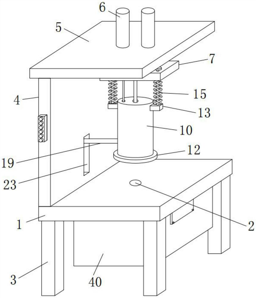
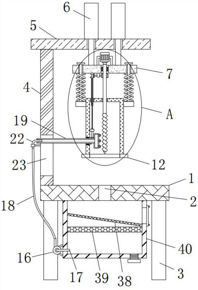
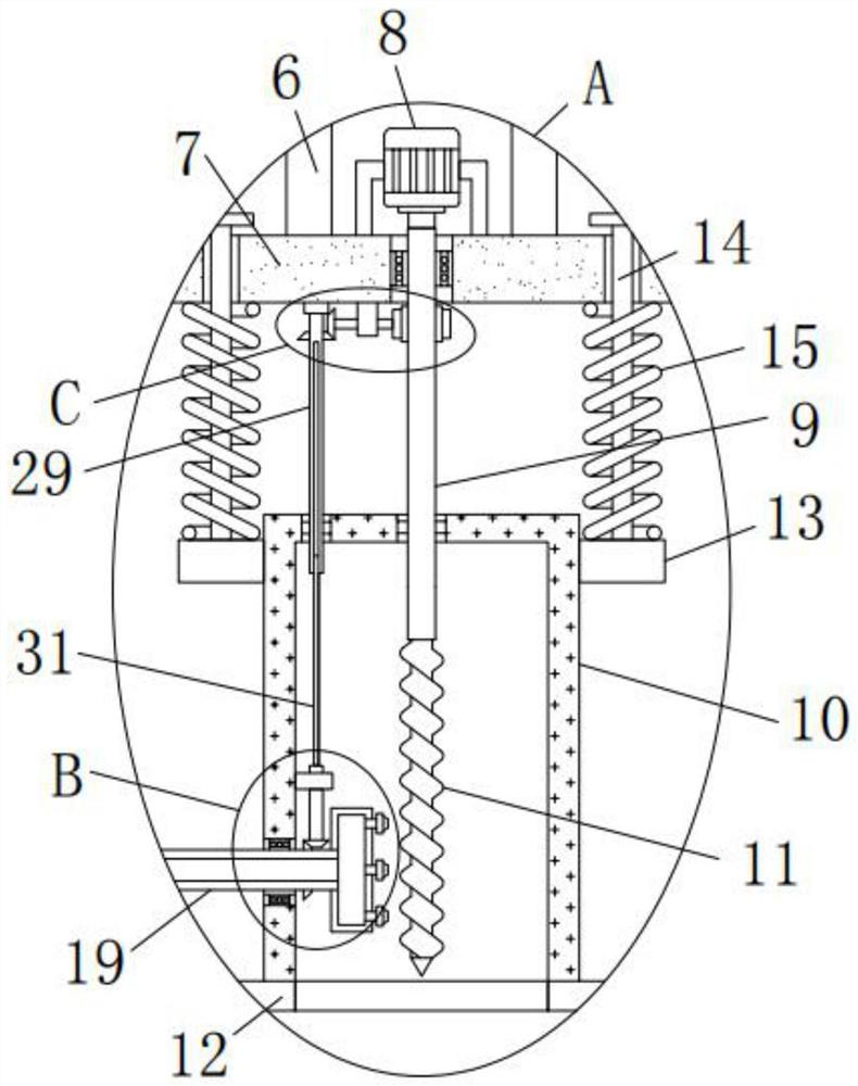
[0030]The purpose of the present invention is to provide a drilling machine tool with a cooling liquid purification and recovery mechanism, so as to solve the problems existing in the above-mentioned prior art, and to recover, purify and recycle the cooling liquid.

[0031] In order to make the above objects, features and advantages of the present invention more clearly understood, the present invention will be described in further de...


PUM


Abstract

The invention discloses a drilling machine tool with a cooling liquid purifying and recycling mechanism, and relates to the technical field of drilling, the drilling machine tool comprises a platform provided with a blanking hole, an air cylinder is fixedly installed at the top of a transverse plate located above the platform, and the output shaft end of the air cylinder penetrates through the transverse plate and then is provided with a lifting plate; a motor in transmission connection with the vertical shaft is fixedly installed at the top of the lifting plate, an isolation barrel with an opening in the bottom is arranged below the lifting plate, the bottom end of the vertical shaft slidably penetrates through the isolation barrel and is fixedly provided with a drill bit, the isolation barrel is connected with the lifting plate through a pressing mechanism, and a cooling liquid conveying mechanism communicated with the interior of the isolation barrel is arranged on the platform. A cooling liquid purifying and recycling mechanism is arranged at the bottom of the platform and comprises a liquid storage tank with an opening in the top, and a purifying assembly is arranged in the liquid storage tank; the cooling liquid can be recycled after being recycled and purified, waste of the cooling liquid is reduced, and resources are saved.

Description

technical field [0001] The invention relates to the technical field of drilling, in particular to a drilling machine tool with a cooling liquid purification and recovery mechanism. Background technique [0002] A drilling machine is a machine tool that uses a drill to drill holes on a workpiece. Its working principle is to use a drill tool that is harder and sharper than the target to leave a hole on the target by rotary cutting or rotary extrusion. Cylindrical holes or holes. Today, drilling machines are widely used in industrial machinery production, suitable for drilling parts and plates. [0003] However, the commonly used drilling machine tools do not have the function of automatically pressing and fixing the object. Usually, the object is clamped and fixed on the machine tool by manual operation, and then the clamped object is drilled and drilled. After the hole is completed, manually operate to release the fixation of the object. The operation steps of this drilling ...

Claims


Application Information

Patent Timeline
Patent Type & Authority Applications(China)
IPC IPC(8): B23Q1/03B23Q3/00B23B47/22B23Q11/08B23Q11/10
CPCB23Q1/03B23Q11/08B23Q11/10B23Q3/00B23Q11/1069B23Q5/22Y02P70/10
Inventor 张舵张好强金鑫侯锁霞赵红印王鑫阁
Owner NORTH CHINA UNIVERSITY OF SCIENCE AND TECHNOLOGY
Why Eureka
Try Eureka