Production process and device for friction disc assembly of elevator brake

A technology of elevator brakes and production technology, which is applied in the direction of manufacturing tools, grinding devices, grinding/polishing safety devices, etc., which can solve the problems of weak braking force of brakes, low flatness of friction surfaces, and inclined placement of friction plates, etc. The effect of reducing production costs, increasing grinding speed, and eliminating potential safety hazards

Pending Publication Date: 2022-05-27
HENGDA FUJI ELEVATOR
View PDF1 Cites 0 Cited by
  • Summary
  • Abstract
  • Description
  • Claims
  • Application Information

AI Technical Summary

Problems solved by technology

Because the cooling speed of the friction plate may be too fast when it is cooled after hot pressing, a certain deformation may occur, resulting in insufficient flatness of the friction plate, that is, the friction surface on the friction disc assembly has a low flatness, or the mounting plate is used for The flatness of the installation surface where the friction plate is placed is not enough, which may cause the friction plate to be placed obliquely, resulting in poor verticality between the friction surface on the friction disc assembly and the spline hole; both of the above two may cause friction of the friction disc assembly The surface cannot fully fit the traction machine base, so the braking force of the brake may be relatively weak during the period of time after the brake is installed on the traction machine and it cannot meet the design requirements.
After the brake has been used for a period of time, the friction plate will re-form a friction surface that can fully fit the traction machine base after wear and tear, and reach the braking force required by the design of the brake. Therefore, few manufacturers pay attention to the possible insufficient braking force in the early stage of brake use. problem, but after all, there are certain security risks

Method used


Image

  • Production process and device for friction disc assembly of elevator brake
  • Production process and device for friction disc assembly of elevator brake
  • Production process and device for friction disc assembly of elevator brake

Examples


Embodiment Construction

[0021] The present invention will be further described below in conjunction with the accompanying drawings and embodiments, but not as a basis for limiting the present invention.

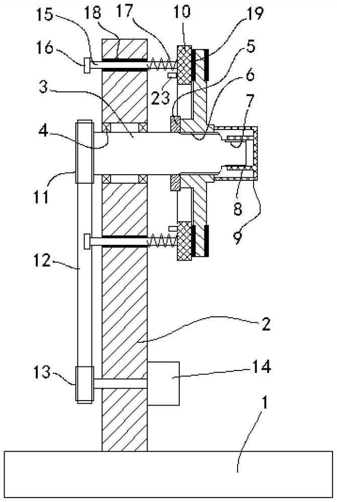
[0022] Example. The production device of the elevator brake friction disc assembly includes a bottom plate 1, a vertical plate 2 is arranged on the bottom plate 1, a horizontal rotating shaft 3 is arranged on the vertical plate 2, the rotating shaft 3 is connected to the vertical plate 2 through a deep groove ball bearing 4, and the vertical plate 2 is arranged on the rotating shaft 3. A drive mechanism is provided, a limit ring 5 is provided on the rotating shaft 3, and the side of the limit ring 5 away from the deep groove ball bearing 4 is provided with a spline part 6 and a thread part 7 in turn, and the diameter of the thread part 7 is smaller than the spline part 6, The rotating shaft 3 is connected to the threaded part 7 through the spline part 6. The threaded part 7 is provided with a screw ...


PUM


Abstract

The invention discloses a production process and device for a friction disc assembly of an elevator brake, friction plates on two sides of the friction disc assembly are respectively ground, during grinding, a grinding agent is continuously added to a grinding surface, and the grinding agent comprises the following components in parts by weight: 30-40 parts of boron carbide powder, 15-20 parts of oleic acid, 1-5 parts of paraffin, 2-4 parts of a dispersant and 2-4 parts of activated carbon powder; the specification of the boron carbide powder is 150-270 meshes, and the mesh number of the activated carbon powder is smaller than that of the boron carbide powder. The friction plate assembly has the advantage that the friction plate assembly can be comprehensively attached to the traction machine base, it is ensured that the brake has large braking force in the early stage of use, the requirement is met, potential safety hazards are eliminated, the production cost is low, and the production speed is high.

Description

technical field [0001] The invention belongs to the field of elevator brake friction disc assemblies, and in particular relates to a production process and device for elevator brake friction disc assemblies. Background technique [0002] The traction machine of the elevator relies on the brake for braking. The friction disc assembly is a key component of the brake, such as the friction disc assembly in the multi-circuit electromagnetic brake in the application number: 202111075635.4 (named in the patent). Disk, the step portion protruding to both sides on the axis of the mounting plate, the step portion is provided with a spline hole connected to the main shaft of the traction machine, and the two end faces of the step portion are finished, as a reference for processing the spline hole On the surface, friction plates are provided on both sides of the mounting plate, and the friction plates are used to increase the friction force of the brake, that is, to improve the braking ...

Claims


Application Information

Patent Timeline
Patent Type & Authority Applications(China)
IPC IPC(8): B24B37/02B24B37/34B24B57/02B24B55/06C09K3/14
CPCB24B37/02B24B37/34B24B37/345B24B57/02B24B55/06C09K3/1409
Inventor 陈锋陶志耀罗世友陈芸芸唐利芳张贤张宁宁宇婷唐玲玲欧阳丽夏伟翁丽曼
Owner HENGDA FUJI ELEVATOR
Why Eureka
Try Eureka