Eureka AIR delivers breakthrough ideas for toughest innovation challenges, trusted by R&D personnel around the world.

Industrial robotic arm for controlling industrial numerical control machine tool

A technology for CNC machine tools and industrial machines, applied in the field of robotic arms, can solve problems such as time-consuming, claw maintenance or replacement process troublesome, and lower overall equipment use efficiency, to achieve the effect of improving use efficiency and shortening operation time.

Inactive Publication Date: 2022-05-27
维徕智能科技东台有限公司
View PDF0 Cites 0 Cited by
  • Summary
  • Abstract
  • Description
  • Claims
  • Application Information

AI Technical Summary

Problems solved by technology

It can move any object or tool according to the time-varying requirements of the space pose, so as to complete the operation requirements of a certain industrial production, and the combination of the two further optimizes the automation of CNC machine tool control and improves work efficiency. The outermost movable arm of some industrial robot arms will be equipped with jaws selected according to actual needs, but the connection method is mostly fixed by hard contact such as bolt locking or welding, and the maintenance or replacement of the jaws is also very troublesome and time-consuming. , reducing overall equipment efficiency

Method used


Image

  • Industrial robotic arm for controlling industrial numerical control machine tool
  • Industrial robotic arm for controlling industrial numerical control machine tool
  • Industrial robotic arm for controlling industrial numerical control machine tool

Examples


Embodiment 1

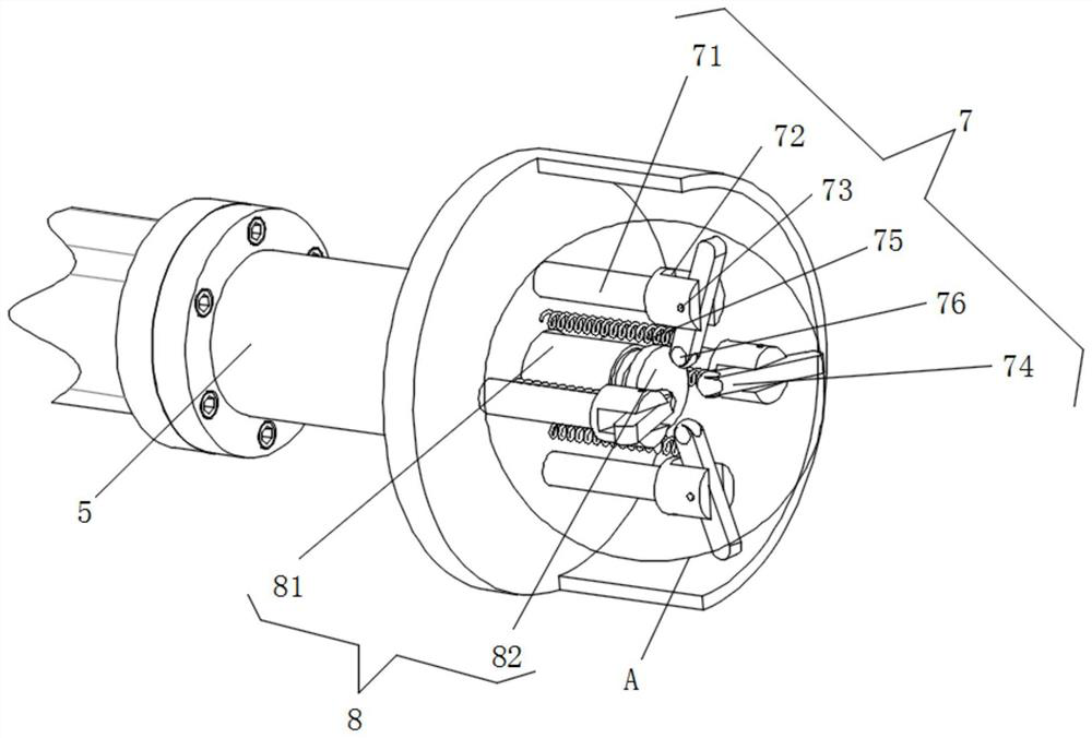
[0033] When it is necessary to provide installation for the jaw, the connection socket 91 set inside the compression support member 91 may first be in the gap between the inner side of the extension sleeve 6 and the clamping member 7, and during the insertion process, in order to avoid the clamping rod 74 interfering with the movement of the connecting socket 91, the clamping lever 74 may be flipped at the beginning of the set of the connecting socket 91, so that the clamping lever 74 is parallel to the extension sleeve 6, the first compression spring 75 at this time is compressed, after the connection socket 91 set to the inside of the extension sleeve 6, Start clamping the electric pushrod 81 inside the power member 81, and then by the electric push rod 81 inside the telescopic rod push magnet top plate 82 for linear movement, and the magnet top plate 82 during the movement will be in contact with the metal sphere 76 inside the clamping member 76 and top pressure, and finally th...

Embodiment 2

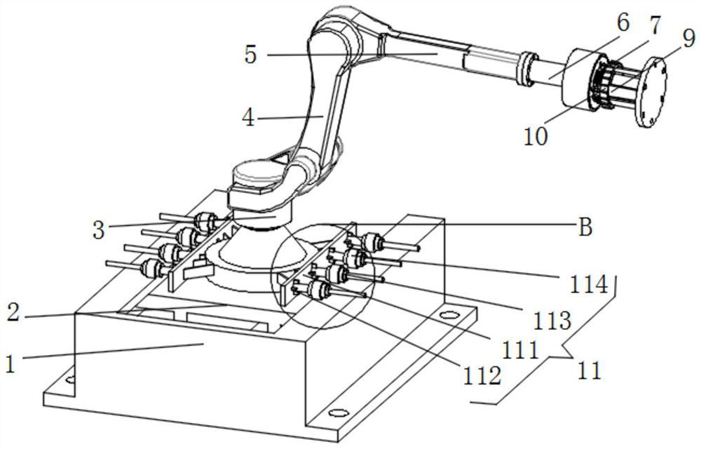
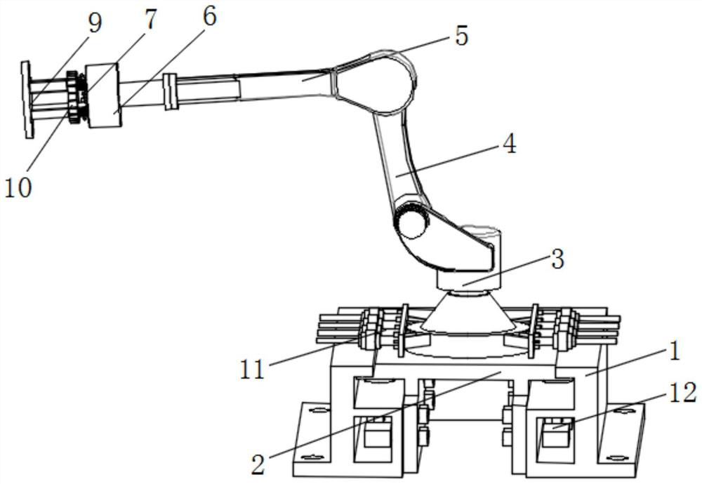
[0035]When the overall equipment in the process of use due to vibration or due to improper operation and impact, at this time the two sets of displacement monitoring mechanism 11 inside the multiple top pressure rod 112 and the pressure sensor 113 between the connection will be displaced intermittently, the specific pressure value change of a plurality of pressure sensors 113 combined to see, reflecting the bottom of the robot arm 3 in the use of the process of displacement changes relative to the original coordinates of the zero point and the specific number of pressure rods 112 and pressure sensor 113 according to the actual use needs set.


PUM


Abstract

The invention relates to the technical field of mechanical arms, and discloses an industrial mechanical arm for controlling an industrial numerical control machine tool, which comprises a first base, a second base, a bottom mechanical arm, a middle-end mechanical arm and a front-end mechanical arm, and one ends of the bottom mechanical arm, the middle-end mechanical arm and the front-end mechanical arm are connected pairwise. The other end of the bottom mechanical arm is connected to the top of the second base. After the extending sleeve, the clamping component, the clamping power component, the pressed supporting component and the secondary locking component are assembled and matched, the clamping and locking auxiliary mechanical arm is formed and serves as an extending structure of a front-end mechanical arm, and besides installation support and stable use support are provided for a specified clamping jaw subsequently, the clamping and locking auxiliary mechanical arm is used for clamping and locking. The extension sleeve and the pressed supporting component can be rapidly separated and replaced under the clamping and locking effects of the clamping power component, the clamping component and the secondary locking component, the maintenance or replacement operation time of workers is shortened, and the use efficiency of the whole equipment is improved.

Description

Technical field [0001] The present invention relates to the technical field of robotic arms, specifically an industrial robotic arm for industrial NUMERICAL machine tool control. Background [0002] CNC machine tool is the abbreviation of digital control machine tool, is an automated machine tool equipped with a program control system. The control system can logically process the program having a control code or other symbolic instructions specified, and it is decoded, represented by coded numbers, and input to the numerical control device through the information carrier. After the operation processing by the numerical control device to send a variety of control signals, control the action of the machine tool, according to the shape and size required by the drawing, automatically process the parts out, and with the continuous development of science and technology, the control of the CNC machine tool and the industrial robot arm combined, the industrial robot arm is an anthropomor...

Claims


Application Information

Patent Timeline
Patent Type & Authority Applications(China)
IPC IPC(8): B25J18/00B25J19/00
CPCB25J18/00B25J19/00Y02P90/02
Inventor 吴晶晶刘一达吴琼
Owner 维徕智能科技东台有限公司
Why Eureka
Eureka Blog
Learn More