Supercharge Your Innovation With Domain-Expert AI Agents!

Magnetic fluid sealing device

A magnetic fluid seal and sealing device technology, which is applied to engine seals, mechanical equipment, engine components, etc., can solve problems such as deformation of transmission structural parts, long equipment downtime, failure of magnetic fluid seals, etc., to reduce replacement and downtime The frequency of replacing spare parts and the effect of improving work efficiency

Pending Publication Date: 2022-05-31
HANGZHOU DAHE THERMO MAGNETICS CO LTD
View PDF0 Cites 0 Cited by
  • Summary
  • Abstract
  • Description
  • Claims
  • Application Information

AI Technical Summary

Problems solved by technology

Lead to magnetic fluid seal failure, leakage, and wear of seals; deformation, wear, and jamming of transmission structural parts
Need to replace spare parts, long equipment downtime

Method used


Image

  • Magnetic fluid sealing device
  • Magnetic fluid sealing device
  • Magnetic fluid sealing device

Examples


Embodiment 1

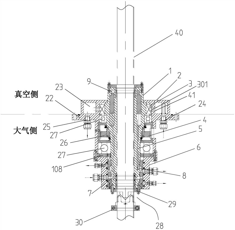
[0048] In the embodiment shown in Fig. 1, a magnetic fluid seal device includes a magnetic fluid seal assembly 3, the magnetic fluid seal assembly 3 is integrated on a body shaft 1, and the magnetic fluid seal assembly 3 below A transmission mechanism assembly 4 is integrated on the body shaft 1, a base 2 with a cooling structure is provided outside the magnetic fluid seal assembly 3 and the transmission mechanism assembly 4, and a body shaft 1 below the transmission mechanism assembly 4 is provided with Body shaft cooling seal assembly 6, said body shaft cooling seal assembly 6 communicates with the inside of the body shaft to form a body shaft cooling system. The body shaft cooling seal assembly 6 is arranged on the body shaft 1 below the base 2 and is in sealing contact with the base 2. The body shaft cooling seal assembly 6 communicates with the body shaft 1 to form a body shaft liquid cooling system.

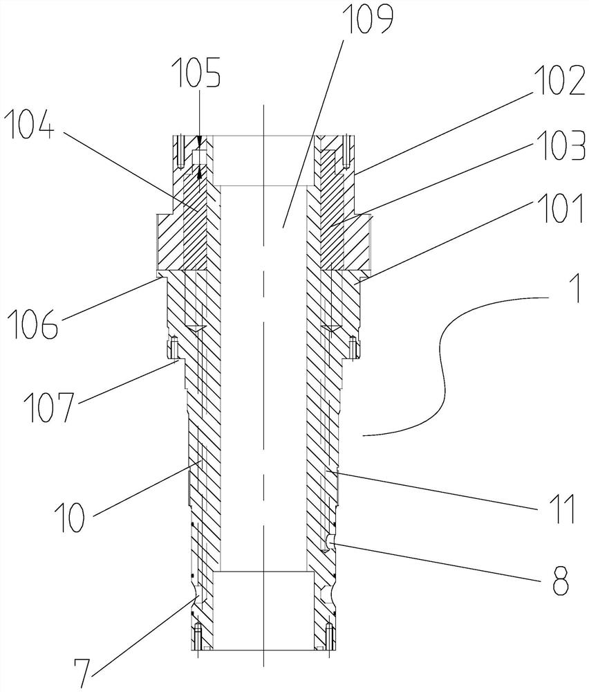
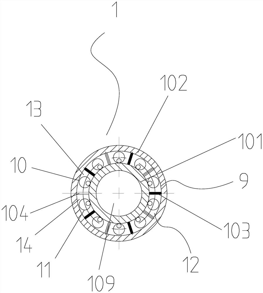
[0049] The inside of the body shaft 1 is provided with a number of coo...

Embodiment 2

[0063] exist Figure 16 , Figure 17 In the shown embodiment, its technical solution is basically the same as that of Embodiment 1, except that: the body shaft cooling seal assembly 6 is arranged on the body shaft 1 inside the base 2 to form an integral sealing structure, and the The body shaft cooling seal assembly 6 communicates with the inside of the body shaft to form a gas cooling system for the body shaft.

[0064] In this embodiment, the body shaft cooling seal assembly 6 includes a magnetic pole 1 6-1, a magnetic pole 2 6-2, a closed magnetic block structure and a magnetic pole locking gland 6-5; the magnetic pole 1 6-1 and The second magnetic pole 6-2 is respectively sleeved on the main body shaft 1 from top to bottom and is dynamically sealed with the main body shaft 1 through a closed magnetic field structure. The inner wall of the static sealing fit; such as Figure 18 As shown, in this embodiment, two sealing grooves 6-9 are respectively arranged on the outer d...


PUM


Abstract

The invention discloses a magnetic fluid sealing device which comprises a magnetic fluid sealing assembly, the magnetic fluid sealing assembly is integrated on a body shaft, a transmission mechanism assembly is integrated on the body shaft, and a base with a cooling structure is arranged outside the magnetic fluid sealing assembly and the transmission mechanism assembly. And a body shaft cooling sealing assembly which is communicated with the interior of the body shaft to form a body shaft cooling system is arranged on the body shaft. Circulating cooling structures are arranged on the inner diameter portions and the outer diameter portions of the regional positions of the magnetic fluid sealing device and the magnetic fluid sealing assembly, the lower portion of a body shaft is assembled with an independent body shaft cooling sealing assembly, and cooling fluid or cooling gas is input from the lower portion of the body shaft in the radial direction, flows to the upper portion through multiple channels after flow division and flows back to the lower portion after circulation. Outputting from the radial direction; and comprehensive cooling of the body shaft is achieved, and the requirement for long-term operation under the high-temperature condition is met. The vacuum sealing device is high in structural integration degree, good in stability and suitable for vacuum sealing of more precise long-axis and long-stroke equipment.

Description

technical field [0001] The invention relates to the technical field of magnetic fluid sealing devices, in particular to a magnetic fluid sealing device that ensures vacuum tightness when the main shaft is lifted and rotated over a long stroke in a high-temperature environment. Background technique [0002] The magnetic fluid sealing device can input the rotary motion from the atmosphere side to the vacuum side and ensure the vacuum tightness. In the vacuum high-temperature equipment in the semiconductor, single crystal furnace, vacuum coating and other industries, the internal temperature of the vacuum chamber is high, and the magnetic fluid sealing device working in a long-term high-temperature environment requires a cooling structure to prolong the service life of the device. The cooling methods in the prior art include: base inflow cooling (including base inflow cooling magnetic fluid seal assembly) and shaft inflow cooling. For the magnetic fluid seal device of the soli...

Claims


Application Information

Patent Timeline
Patent Type & Authority Applications(China)
IPC IPC(8): F16J15/43F16J15/32F16J15/16
CPCF16J15/43F16J15/32F16J15/162
Inventor 洪婧雷林光陈军
Owner HANGZHOU DAHE THERMO MAGNETICS CO LTD
Features
  • R&D
  • Intellectual Property
  • Life Sciences
  • Materials
  • Tech Scout
  • Unparalleled Data Quality
  • Higher Quality Content
  • 60% Fewer Hallucinations
Learn More