
Transition tube for gas turbine can combustor

A gas turbine and transition pipe technology, which is applied in gas turbine installations, combustion chambers, combustion equipment, etc., can solve problems such as affecting structural strength

Pending Publication Date: 2022-05-31
ANSALDO ENERGIA SWITZERLAND AG
View PDF0 Cites 0 Cited by
  • Summary
  • Abstract
  • Description
  • Claims
  • Application Information

AI Technical Summary

Problems solved by technology

However, this thickness reduction may adversely affect the structural strength of the member

Method used


Image

  • Transition tube for gas turbine can combustor
  • Transition tube for gas turbine can combustor
  • Transition tube for gas turbine can combustor

Examples


Embodiment Construction

[0041]In conjunction with the accompanying drawings, the technical content and detailed description of the present invention are hereinafter described according to preferred embodiments, and are not intended to limit the implementation scope thereof. Any equivalent changes and modifications made in accordance with the appended claims are all covered by the claimed invention.

[0042] The present invention will now be described in detail with reference to the accompanying drawings.

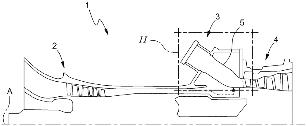
[0043] see figure 1 , figure 1 is a side elevation view of a gas turbine assembly, which may be provided with a plurality of transition ducts according to the present invention, taken along an axial longitudinal plane. in particular, figure 1 A simplified view of a gas turbine assembly generally indicated at 1 is disclosed. Gas turbine assembly 1 includes a compressor 2 , a combustor assembly 3 and a turbine 4 . The compressor 2 and the turbine 4 extend along a main axis A. figure 1 The burne...


PUM


Abstract

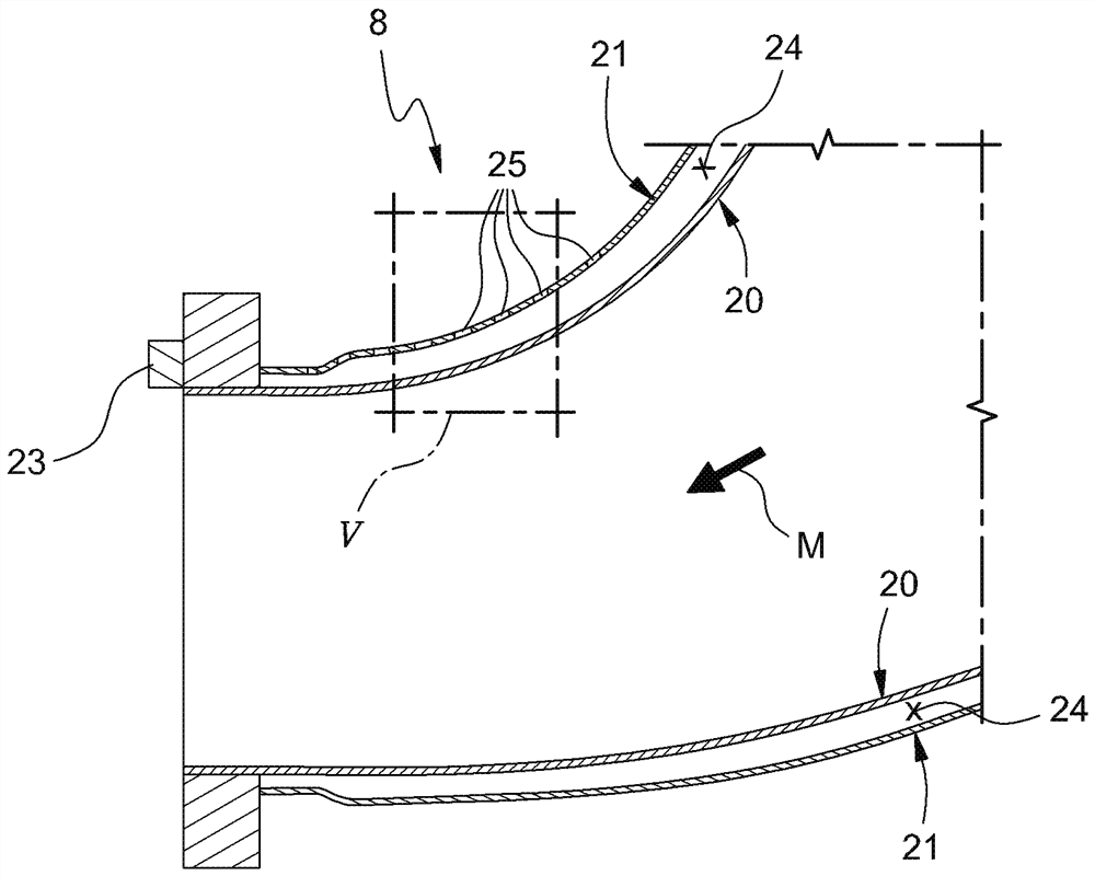
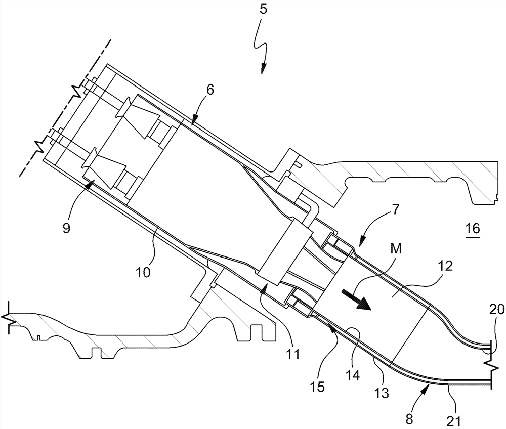
A transition tube for a can combustor for a gas turbine assembly of a power plant; the transition tube is a tubular assembly including a first end configured for coupling to a combustion chamber of a barrel combustor and a second end configured for coupling to a turbine of a gas turbine assembly; the transition tube includes: an inner tubular body having an inner surface in contact with a hot gas, and an outer surface; an outer tubular body having an inner surface and an outer surface in contact with cooling air; wherein there is a gap between the inner tubular body and the outer tubular body to form a cooling channel defined by an outer surface of the inner tubular body and an inner surface of the outer tubular body; wherein the outer tubular body is provided with a plurality of holes for allowing cooling air to enter the cooling channel; wherein the outer surface of the inner tubular body is provided with a plurality of ribs.

Description

[0001] Cross References to Related Applications [0002] This patent application claims priority from European Patent Application No. 20210265.3 filed on November 27, 2020, the entire disclosure content of which is hereby incorporated by reference. technical field [0003] The technical field of the invention relates to the field of gas turbine assemblies for power plants. In particular, the present invention relates to transition ducts for gas turbine can combustors, wherein the term "transition duct" means, as known to those skilled in the art, Assembly directs hot gases to the downstream components of the can combustor. In this technical field, the present invention concerns the technical problem of how to improve the cooling of the transition duct above in order to allow an increase in the temperature of the hot gas. Furthermore, the invention relates to a can combustor provided with a transition duct as described above, and to a gas turbine for a power plant comprising ...

Claims


Application Information

Patent Timeline
IPC IPC(8): F23R3/60F01D9/02F02C3/04
CPCF23R3/60F01D9/023F02C3/04F01D25/12F05D2260/201F05D2230/30
Inventor S·索普P·孟
Owner ANSALDO ENERGIA SWITZERLAND AG
Learn More