
Full-automatic lens centering edge grinding machine

A kind of edging machine, fully automatic technology, applied in the direction of machine tools suitable for grinding the edge of workpieces, parts of grinding machine tools, grinding machines, etc., can solve the problems of affecting the effect of lens edging, low precision, and unguaranteed yield rate, etc. Achieve the effects of improving convenience and automation efficiency, high yield and production efficiency, and improving surface processing quality

Pending Publication Date: 2022-06-03
中山市光维智能科技有限公司
View PDF0 Cites 0 Cited by
  • Summary
  • Abstract
  • Description
  • Claims
  • Application Information

AI Technical Summary

Problems solved by technology

[0003] 1. When the existing centering and edging machine is loaded, the lens is usually loaded and clamped manually. The degree of automation is low, not only the labor cost is high, the production efficiency is low, and the lens will inevitably be misaligned or dropped when placed manually. Phenomenon, the yield rate cannot be guaranteed;
[0004] 2. Because the traditional clamping device uses two motors to drive the two clamp shafts to rotate respectively, it usually cannot drive the lens to rotate at high speed when centering. The speed of the clamp shaft is generally less than 100r / min. If the speed is too fast, it is easy to cause eccentricity and scratches due to asynchrony Damage the lens, resulting in low processing efficiency and affecting the edge grinding effect of the lens;
[0005] 3. When edging, the edging position is fixed, and the lens cannot be edging in multiple directions, resulting in low edging efficiency, poor processing effect and low precision

Method used


Image

  • Full-automatic lens centering edge grinding machine
  • Full-automatic lens centering edge grinding machine
  • Full-automatic lens centering edge grinding machine

Examples


Embodiment Construction

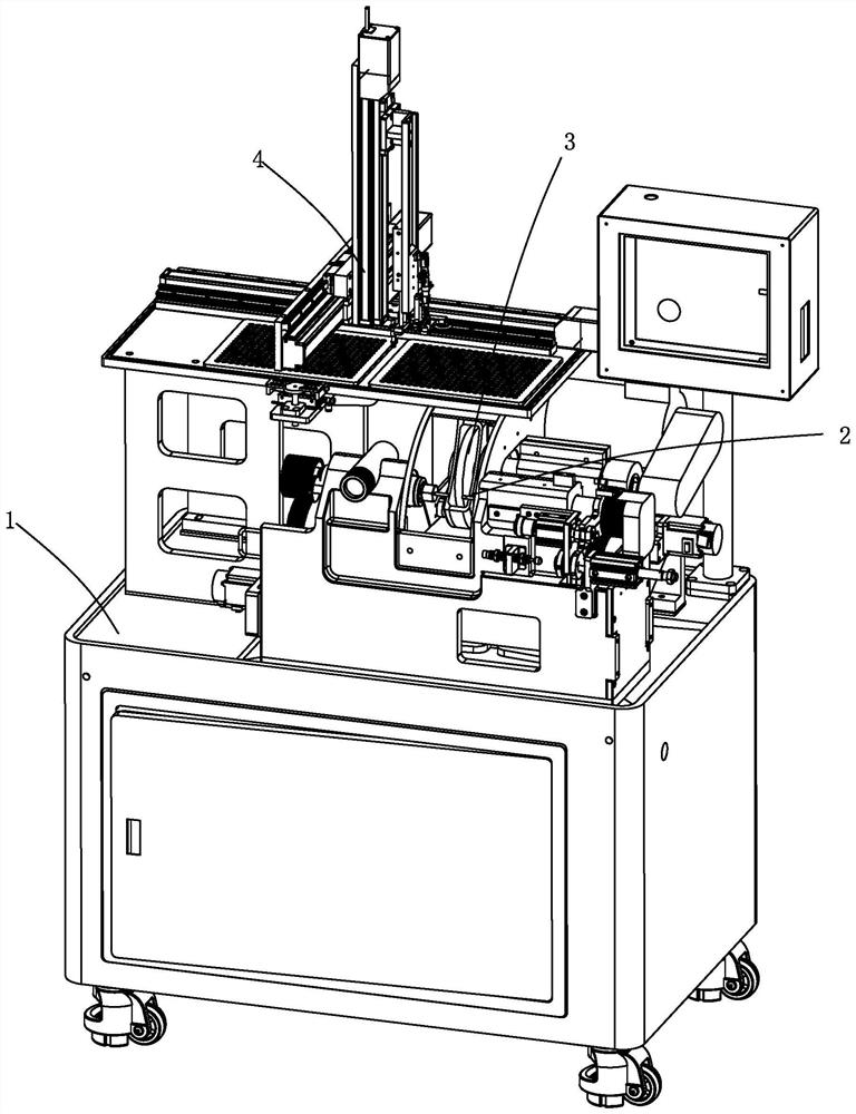
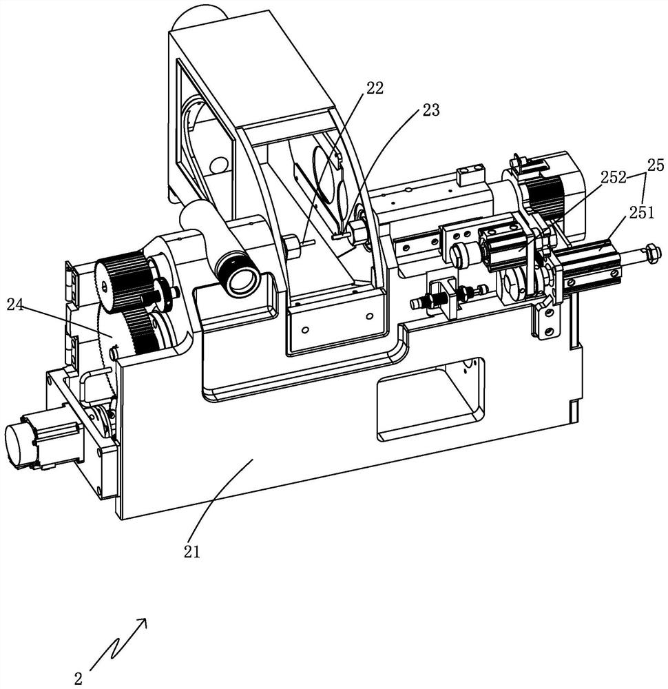
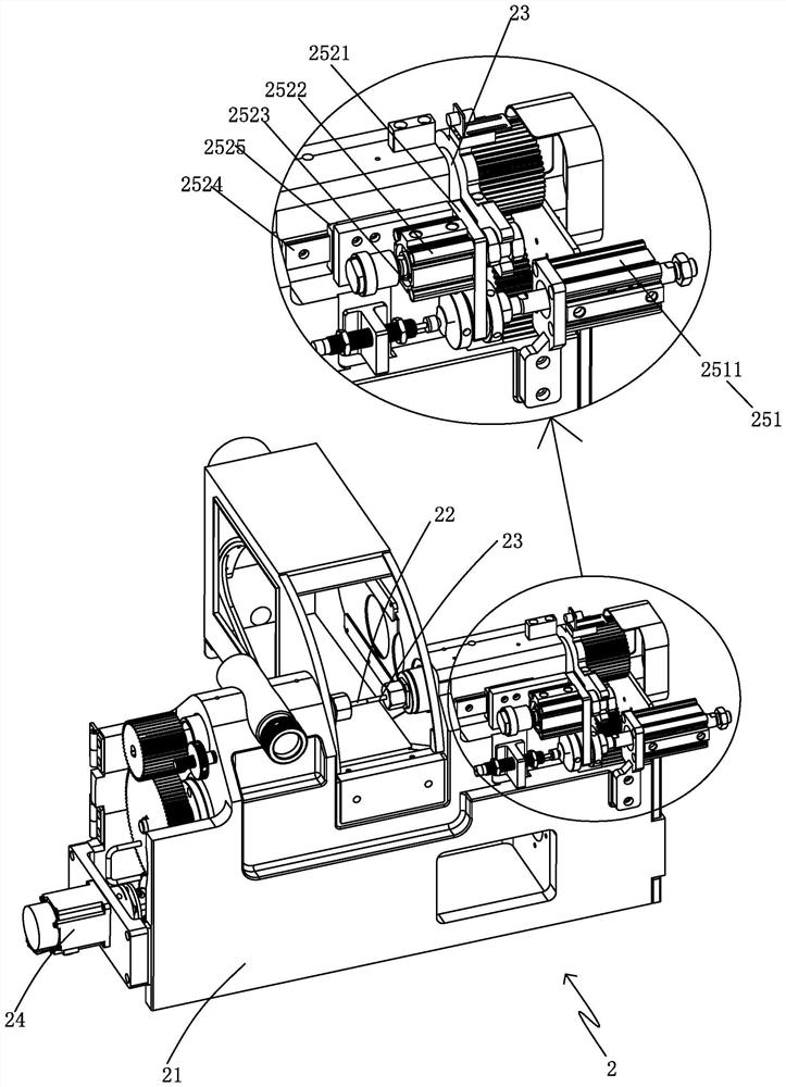
[0054] like Figure 1-12 As shown, the automatic lens centering and edging machine includes a body 1, and the body 1 is provided with a clamping device 2, an edging device 3 and a feeding device 4;

[0055] The present application provides an automatic lens centering and edging machine, which includes a body, a clamping device, an edging device and a feeding device. The feeding device automatically corrects and moves the lens to be processed to the clamping device for feeding, and the clamping device The lens to be processed is first adsorbed and then clamped, and then the clamping shaft rotates synchronously, relying on centrifugal force and clamping force to automatically align the lens to the center, and then the edging device moves horizontally relative to the lens to perform multi-directional precise edging processing. The device takes out and unloads the lens from the clamping device, and the present application has a simple structure, improves the convenience and automa...


PUM


Abstract

The invention provides a full-automatic lens centering edge grinding machine which comprises a machine body, a clamping device, an edge grinding device and a feeding device, a to-be-machined lens is automatically corrected through the feeding device and then moved to the clamping device for feeding, the clamping device firstly adsorbs the to-be-machined lens and then clamps the to-be-machined lens, then a clamping shaft is driven to synchronously rotate, and the to-be-machined lens is clamped through the clamping shaft; the lens is automatically aligned to the center by means of centrifugal force and clamping force, then the edge grinding device horizontally moves relative to the lens to carry out multi-directional accurate edge grinding machining, after machining is completed, the feeding device takes out the lens from the clamping device and carries out discharging, the structure is simple, the lens machining convenience and automation efficiency are improved, and the lens machining precision can be ensured.

Description

technical field [0001] The application belongs to the technical field of optical lens processing equipment, in particular to an automatic lens centering and edging machine. Background technique [0002] The lens centering and edging machine processes the lens, and it goes through the steps of feeding, clamping, centering, and edging in sequence. The existing centering and edging machines have the following defects or problems: [0003] 1. When the existing centering and edging machine is feeding, the lens is usually loaded and clamped manually. The degree of automation is low, not only the labor cost is high, but the production efficiency is low, and manual placement of the lens will inevitably lead to misalignment or falling, etc. phenomenon, the yield rate cannot be guaranteed; [0004] 2. Since the traditional clamping device uses two motors to drive the two clamp shafts to rotate, the lens cannot be rotated at high speed during centering. The speed of the clamp shaft is...

Claims


Application Information

Patent Timeline
IPC IPC(8): B24B9/14B24B41/00
CPCB24B9/14B24B9/146B24B41/005Y02P40/57
Inventor 饶龙军陈明聪谢扬德丁立煜宋超张静
Owner 中山市光维智能科技有限公司
Learn More