Waste recovery equipment for stainless steel band production

A technology of scrap recycling and stainless steel strips, applied in metal processing equipment, other manufacturing equipment/tools, manufacturing tools, etc., can solve the problems of deformation of rolled pieces, easy to be sucked into the body, waste of raw materials, etc. The effect of reducing hidden dangers such as burns and reducing burrs

Inactive Publication Date: 2022-06-07
陈榕
View PDF0 Cites 0 Cited by
  • Summary
  • Abstract
  • Description
  • Claims
  • Application Information

AI Technical Summary

Problems solved by technology

[0002] The steel strip needs to be annealed during the production process. The conveying steel strip is prone to deformation and damage at high temperature. After rolling, the temperature of the rolled piece on the cooling bed is relatively high. A certain degree of deformation is caused, and the edge of the steel strip is not neat. Therefore, the raw edge of the steel strip must be cut through the edge trimming device. Will affect the progress of product production
At the same time, due to the different size requirements of customers for steel strips, some large-sized steel strips need to be cut, and scraps often appear during the cutting process. If these scraps are discarded, raw materials will be wasted, so scraps need to be recycled, but Due to the continuous cutting of the steel strip, the length of the leftover material is too long, and some burrs will grow during the cutting process. If it is collected manually, there will be a safety hazard, and some powder-shaped debris will also be produced during the cutting process. Small, if left unattended, it will affect the air quality on the workstation, and it is easy to be inhaled into the body. Therefore, based on the above problems, an innovative design of the device is carried out

Method used


Image

  • Waste recovery equipment for stainless steel band production
  • Waste recovery equipment for stainless steel band production
  • Waste recovery equipment for stainless steel band production

Examples


Embodiment Construction

[0026] In order to make it easy to understand the technical means, creation features, achieved goals and effects of the present invention, the present invention will be further described below with reference to the specific embodiments.

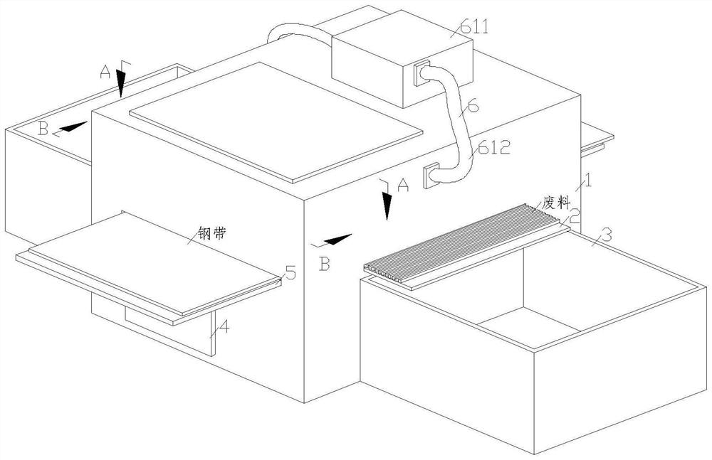
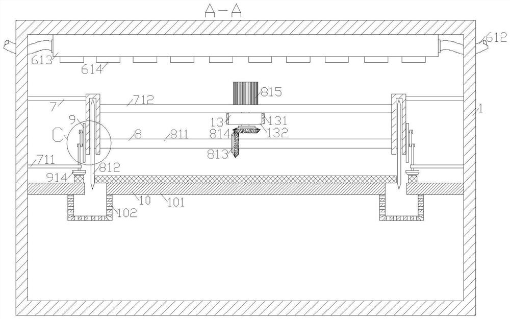
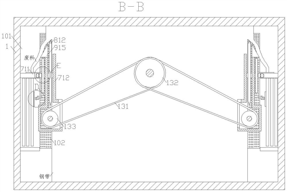
[0027] like Figure 1-Figure 5 As shown, a kind of waste recycling equipment for stainless steel strip production according to the present invention includes a device box 1, a discharging rack 2 and a feeding rack 5, and the feeding rack 5 is respectively fixed and arranged in the middle of the front and rear sides of the device box 1. , and the discharge rack 2 is fixedly installed on the front and rear sides of the device box 1, the collection box 3 is fixedly installed on the device box 1 on the lower side of the discharge rack 2, and the gas transmission mechanism 6 is fixedly installed on the upper side of the device box 1, and the gas transmission The mechanism 6 can be fixedly installed inside the device box 1, the support mechanism 10...


PUM


Abstract

The invention relates to the field of steel belt machining, in particular to waste recovery equipment for stainless steel belt production, which comprises a device box, discharging frames and conveying frames, the conveying frames are fixedly arranged in the middles of the front side and the rear side of the device box in a penetrating manner, and the discharging frames are fixedly mounted on the front side and the rear side of the device box respectively; a collecting box is fixedly installed on the device box on the lower side of the discharging frame, a gas conveying mechanism is fixedly installed on the upper side of the device box and can be fixedly installed in the device box, a supporting mechanism is fixedly installed in the middle of the inner side of the device box, and a steel belt cutting mechanism is fixedly installed on the upper side of the supporting mechanism. The waste cutting mechanisms are fixedly mounted on the front side and the rear side of the steel belt cutting mechanism correspondingly, the pushing mechanism is fixedly connected to the left sides of the waste cutting mechanisms, the polishing mechanisms are tightly attached to the front side and the rear side of the cut steel belt, and the polishing mechanisms are fixedly connected with the steel belt cutting mechanism. And polishing treatment and heat dissipation can be conducted on the steel belt.

Description

technical field [0001] The invention relates to the field of steel strip processing, in particular to a waste recycling device for stainless steel strip production. Background technique [0002] The steel strip needs to be annealed in the production process. The conveying steel strip is prone to deformation and damage at high temperature. The temperature of the rolled piece after being rolled is higher after being placed on the cooling bed. During the cooling process, due to the effect of thermal expansion and contraction, the rolled piece will be damaged. It will cause a certain degree of deformation and cause the edge of the steel strip to be uneven. Therefore, it is necessary to escape the edge trimming device to cut the burr of the steel strip. However, the cut edge material is usually put on hold first. During the shelving period, there is not only a potential safety hazard, but also a problem. It will affect the progress of product production. At the same time, due to...

Claims


Application Information

Patent Timeline
Patent Type & Authority Applications(China)
IPC IPC(8): B23P23/04B23Q11/00B23Q11/10B23Q5/10B23Q7/00
CPCB23P23/04B23Q11/0042B23Q11/005B23Q11/10B23Q5/10B23Q7/00Y02P70/10
Inventor 陈榕卢伟
Owner 陈榕
Why Eureka
Try Eureka