Model body and calibration method suitable for geometric correction of common track cone beam CT system

A technology of geometric correction and calibration method, which is applied in the directions of instruments, applications, and image enhancement for radiological diagnosis.

Pending Publication Date: 2022-06-07
SOUTHEAST UNIV +1
View PDF0 Cites 2 Cited by
  • Summary
  • Abstract
  • Description
  • Claims
  • Application Information

AI Technical Summary

Problems solved by technology

[0003] The reconstruction algorithm of the cone beam CT system has strict requirements on the imaging geometry, which is called the ideal geometry, but in actual situations, the actual geometry deviates from the ideal geometry due to installation errors and processing errors
In this case, continuing to use the ideal geometry for image reconstruction will result in geometric artifacts in the reconstructed image, affecting image quality
Generally, the geometric trajectory of the cone beam CT system is a circular trajectory. For such a system, there are many methods to correct the geometric parameters. However, with the improvement of the resolution of the cone beam CT system, it is difficult to guarantee the standard circular trajectory. , and there are many other special scanning requirements that require that the scanned trajectory is not a circular trajectory, which requires high-precision geometric correction for the general trajectory cone beam CT system
To realize the high-precision geometric correction of the general trajectory cone beam CT system, it is necessary to formulate a high-precision geometric phantom. The existing methods require high-precision manufacturing equipment to process the phantom, which is very inconvenient for actual use. This patent introduces a Low-cost phantom fabrication and high-precision calibration method

Method used


Image

  • Model body and calibration method suitable for geometric correction of common track cone beam CT system
  • Model body and calibration method suitable for geometric correction of common track cone beam CT system
  • Model body and calibration method suitable for geometric correction of common track cone beam CT system

Examples


Embodiment Construction

[0055] The technical scheme of the present invention is described in detail below by the accompanying drawings, but the scope of protection of the present invention is not limited to the embodiments.

[0056] First, correct the preparation of mold bodies

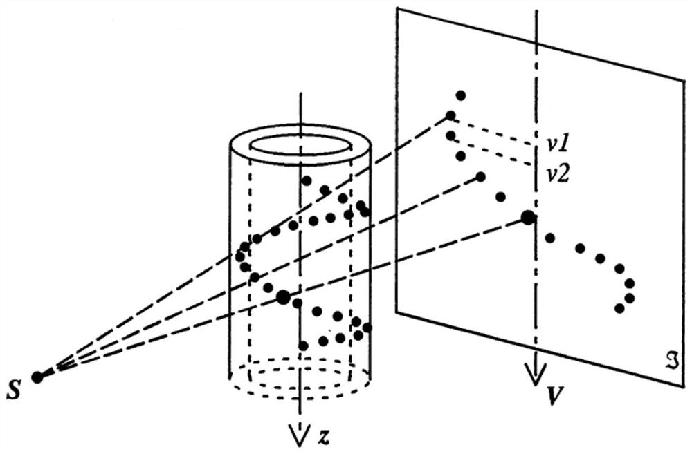
[0057] Figure 1It is a schematic diagram of the three-dimensional structure of the correction mold and the projection result. The correction mold takes the plexiglass cylinder as the main body, in which the spiral is inlaid with N metal balls, N≥5, the size of the pellets is inversely proportional to the resolution of the cone beam CT system, the system with high resolution selects smaller balls, the low resolution system selects larger balls, and the cone beam CT system equipped with a turntable with high circularity and high concentricity is used to scan the correction mold, and the projection data of the balls is obtained through the detector. There are two main reasons for the design of metal pellets as spiral distributions...


PUM


Abstract

The invention discloses a model body and a calibration method suitable for geometric correction of a general trajectory cone beam CT system. The calibration method comprises the following steps: constructing back projection line coastal introduction auxiliary parameter virtual intersection points of a small ball at different angles based on projection data of the small ball; constructing a target function of the back projection line intersection degree according to the virtual intersection point; expanding the objective function to obtain a sum objective function of the N small balls; the optimal solution of the sum objective function is solved through an optimization algorithm, and initial three-dimensional coordinates of the mass centers of the N small balls are obtained; and registering and averaging the initial three-dimensional coordinate values of the N small balls based on a rigid motion registration algorithm of singular value decomposition to obtain an accurate three-dimensional coordinate value which is used as a reference value of the geometric calibration method of any track. The method aims at accurately obtaining high-precision space parameters of the die body without depending on machining precision, and further provides a calibration die body for geometric correction of a common track cone beam CT system, especially a high-resolution cone beam CT system.

Description

Technical field [0001] The present invention relates to the field of image processing technology for computed tomography, specifically to a mold body and calibration method suitable for geometric correction of a general trajectory cone beam CT system. Background [0002] Cone beam CT (ComputerizedTomography) system, through the ray at different angles of the object scanning, the density and thickness of the object fault through the computer tomography image to express out, the reconstruction of the tomography image can obtain the internal image information of the object to be measured, with other nondestructive testing methods can not replace the characteristics, in the field of industrial nondestructive testing has a broad application prospects. [0003] The reconstruction algorithm of the cone beam CT system has strict requirements for the geometry of the image, which is called the ideal geometry, but in the actual situation, the actual geometry will deviate from the ideal geom...

Claims


Application Information

Patent Timeline
Patent Type & Authority Applications(China)
IPC IPC(8): G06T5/00G06T7/80G06T7/00A61B6/00A61B6/03
CPCG06T5/006G06T7/85G06T7/0012A61B6/032A61B6/4085A61B6/583G06T2207/10081
Inventor 李光罗守华董歌施晶晶徐方
Owner SOUTHEAST UNIV
Why Eureka
Try Eureka