
Dynamic bridge form identification method based on computer vision

A technology of computer vision and recognition method, which is applied in the field of visual measurement, can solve problems such as the difficulty of identifying small deformations, increase the cost of sensors and the time for computer processing, and achieve the effects of saving test costs and requiring low parameters for measuring instruments

Pending Publication Date: 2022-06-07
HEFEI UNIV OF TECH
View PDF0 Cites 0 Cited by
  • Summary
  • Abstract
  • Description
  • Claims
  • Application Information

AI Technical Summary

Problems solved by technology

[0003] However, at present, there are still difficulties in identifying small deformations when the sensor pixels are insufficient for the dynamic shape recognition of bridge structures with visual sensors.
When the target structure is large, if you want to record the whole structure for shape recognition, if you do not increase the resolution of the sensor, there will not be enough pixels to capture the small deformation of the structure, and increasing the resolution of the sensor will greatly increase the cost of the sensor and computer processing time

Method used


Image

  • Dynamic bridge form identification method based on computer vision
  • Dynamic bridge form identification method based on computer vision
  • Dynamic bridge form identification method based on computer vision

Examples


Embodiment 1

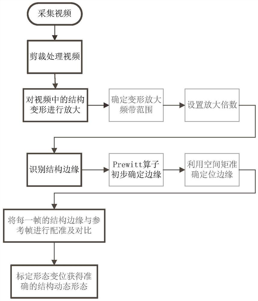
[0041] like figure 1 As shown, a flow chart of a computer vision-based dynamic bridge shape recognition method provided by an embodiment of the present invention includes the following steps:

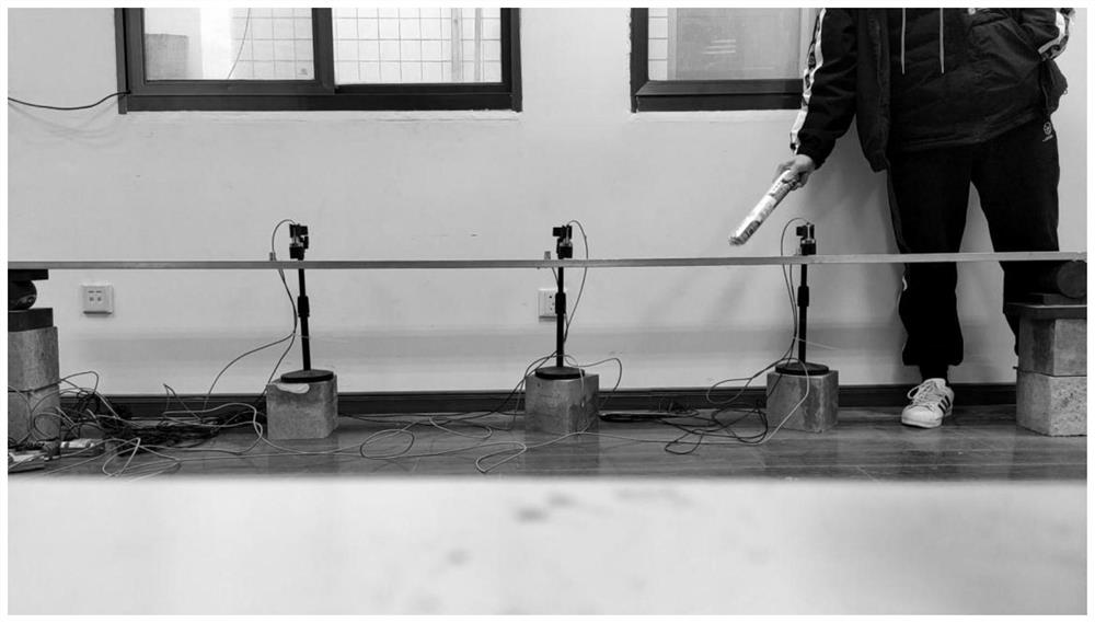
[0042] S1. Select a sensor with a suitable sampling frequency and resolution to capture video of the target structure;

[0043] S2. Cut the collected video to obtain the video of the target area; when using a color vision sensor, the video can be converted into a grayscale color mode to reduce the calculation amount of subsequent computer processing;

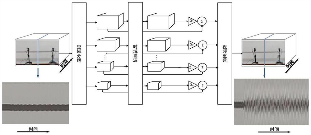
[0044] S3. Use the Euler video magnification algorithm based on brightness change to amplify the structural deformation in the video; its basic principle is mainly based on the optical flow method in the traditional video motion processing, using the spatial consistency of the optical flow and the constant brightness It is assumed that the tiny motion in the video is equivalent to a tiny brightness change, and the indirect processing of ...

Embodiment 2

[0054] A specific computer vision-based dynamic bridge morphology recognition method is provided:


PUM


Abstract

The invention is suitable for the technical field of vision measurement, and provides a dynamic bridge form recognition method based on computer vision, which comprises the following steps: selecting a sensor with proper sampling frequency and resolution to carry out video acquisition; the collected video is cut; amplifying the structural deformation of the video by using an Euler video amplification algorithm; for a target structure in each frame of image after motion amplification, preliminarily determining possible structure edge pixel points by using a Prewitt operator, and then solving the positions of the structure edge points in the region by using a spatial moment sub-pixel edge detection algorithm; obtaining a dynamic form identification result of the structure according to the edge identification point cloud result of each frame; structural deformation recognized by the method is calibrated by using the distance between two pixel points on the surface of a known object in a picture and a video motion amplification coefficient, and accurate dynamic form change is obtained. According to the invention, visual non-contact measurement is realized, a sensor does not need to be installed on the structure, normal operation of the structure is not interfered, and the test cost is saved.

Description

technical field [0001] The invention belongs to the technical field of visual measurement, and in particular relates to a computer vision-based dynamic bridge shape recognition method. Background technique [0002] During the operation stage of the bridge, the deformation of the main girder, the bridge tower and the stay cable directly reflects the structural stiffness of the bridge, so the morphological change of the bridge is an important index to evaluate the mechanical performance of the bridge. Compared with the existing deformation detection methods such as contact displacement meter, laser displacement meter, photoelectric displacement meter, etc., the bridge morphology measurement method based on digital image technology has been developed in recent years. Image to obtain the displacement information of the structure, remote non-contact measurement can be performed without installing sensors, which has the advantages of fast and easy to use, high precision, small res...

Claims


Application Information

Patent Timeline
Patent Type & Authority Applications(China)
IPC IPC(8): G06V20/40G06V10/34G06V10/44
CPCG06T2207/20016G06T2207/10016G06T5/10G06V10/44G06V2201/07G01M5/0008G06T7/50G06T7/0004G06T7/13G06T7/30G06T2207/10028
Inventor 王佐才张飞段大猷辛宇马乐乐
Owner HEFEI UNIV OF TECH
Learn More